126 en | 18VAC Input Power Supply Card Access Easy Controller
Ver 2.0.0 | 2006.07 Hardware Manual Bosch Security Systems
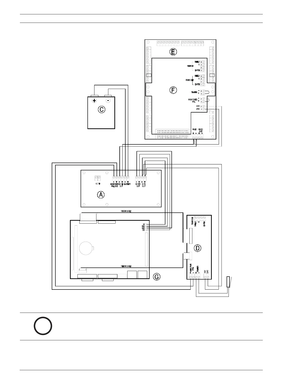
Internal wiring diagram of AEC (UL Listed System)
CN2 CN1
B
PI N 1
PIN 1
CN2
CN1
T1 1
J1
T1
IN
1
1
1
T4
T5
T3
B
T2
B
T1
IN
T1
T2
(P/N: AEC MOD COM)
SECURE COMM. CARD
(P/N: AEC SER EXT)
CONVERTER BOARD
4 READER BOAR D
(P/N: AEC 4W EXT)
12 V 7 AH
BA T TE RY
(P/N: AEC MOD UPS2)
18VAC INPUT POWER SUPPLY BOARD
T3
243
5643 432121 21
4321
1234 21
LA N LA N
COM 1 VGA PORT 2 PORT 1
PI N 1
CN11
(P/N: AEC MOD CPU)
CPU BOARD
PI N 1
CN1
PS2
CHASSIS
TAM P ER SWITCH
i
NOTICE!
This output could only provide a Max. Output of 15VDC at 1A. DO NOT CONNECT ANY HIGH
POWER CONSUMPTION DEVICES TO IT. All other devices, such as Locks, should be supplied
by a separate power source.