Access Easy Controller The CPU Card | en 91
Bosch Security Systems Hardware Manual Ver 2.0.0 | 2006.07
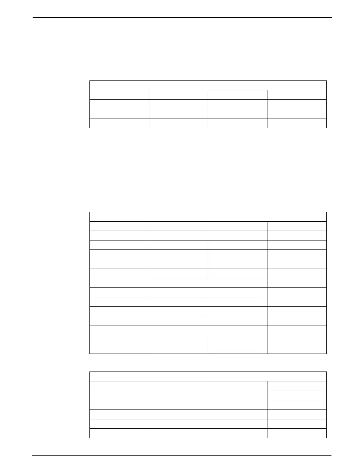
Ethernet Connector
A Category 5 cable is connected from this RJ45 socket to the plug-in 100baseT Ethernet card
located in the Central Monitoring Computer directly or via a hub. The pin configuration for the
socket is shown in the following table: -
Serial Port for Modem
This is a standard RS232 communication port currently used for modem connection
Please refer to Appendix for cable connection and other detail.
Serial Port & Parallel Port Connector for Secure/Communication Card
These are 9pin serial port and 25pin parallel port connectors. These are the links between
CPU Card and Secure/Communication Card. The serial port is connected to the Secure/Com-
munication Card CN2, parallel port is connected to CN1 of Secure/Communication Card.
100Base-Tx Ethernet connector
1 Tx+ 2 Tx-
3Rx+4NC
5NC6Rx-
7NC8NC
Parellel Port
Pin Signal Pin Signal
1 STROBE 2 AUTOFD
3D04ERR
5D16\INT
7D28SLCTINI
9D310GND
11 D4 12 GND
13 D5 14 GND
15 D6 16 GND
17 D7 18 GND
19 ACK 20 GND
21 BUST 22 GND
23 PE 23 GND
25 SLCT
RS232 Serial Port
Pin Signal Pin Signal
1DCDB2RXDB
3TXDB4DTRB
5GND6DSRB
7RTSB8CTSB
9RIB10