1 689 975 233 2018-05-08| Robert Bosch GmbH
62 | EPS 708 | Repairen
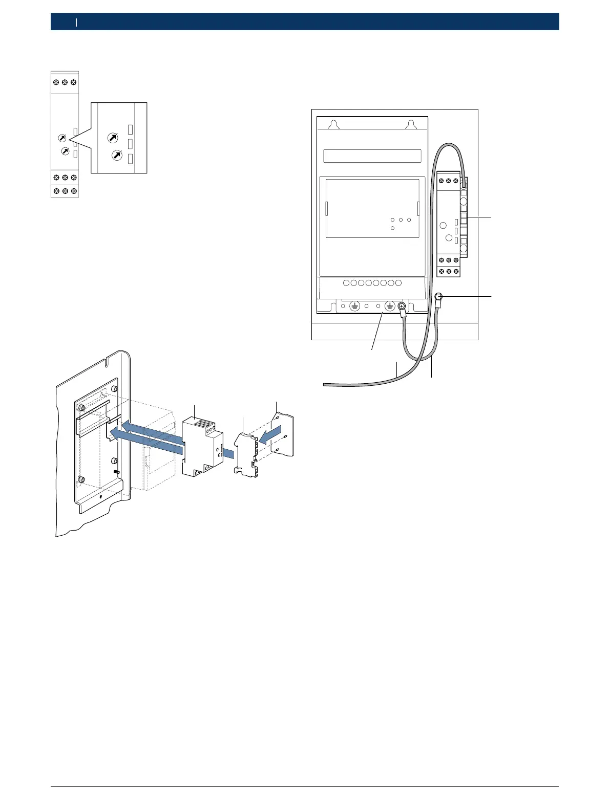
Installing the time delay relay K9
Range
Time
10s
1
Range
Time
10s
1
Fig. 111: Time relay K9
1. Set the delay time to 10 seconds on the time relay
K9 (see Fig. 111). Set the "Range" to 10s and the
"Time" fine adjustment to 1.
2. Attach the time relay K9 (Fig. 112, item 1) to the top
hat rail of the adapter plate.
3. Attach cover (Fig. 112, item3) tothe protective con-
ductor terminal (Fig. 112, item2).
4. Attach protective conductor terminal
(Fig. 112, item2) to top hat rail of the adapter plate.
1
2
3
Fig. 112: Installing the time relayK9 and protectiveconductor
terminal
Connecting the protective conductor
i Follow the supplied circuit diagram 1 689 911 487.
5
2
1
3
4
458859-16_Pal
RUN FWD REV
POWER
Fig. 113: Protective conductor connection
1 Protective conductor terminal
2 Threaded bolt M6
3 Single-core cable GN/YE 4 mm² x 150 mm with 2 x eyelets
4 Single-core cable GN/YE 2.5 mm² x 600 mm with 2 x end ferru-
les
5 Protective conductor bar
1. Connect the single-core cable GN/YE (Fig. 113,
item4)to the protective conductor terminal (Fig. 113,
item 1).
2. Connect the other end of the single-core cable GN/
YE (Fig. 113, item 1)to the protective conductor
terminal 1.2 (see Fig. 103, item 3).
3. Connect the single-core cable GN/YE (Fig. 113,
item3)to the threaded bolt (Fig. 113, item 2) with a
washer, circlip and hex nut M6.
4. Connect the other end of the single-core cable
to the protective conductor bar of the frequency
converter (Fig. 113, item 1). Use the fastening screw
screwed into the frequency converter.