1 689 975 233 2018-05-08| Robert Bosch GmbH
Repair | EPS 708 | 63 en
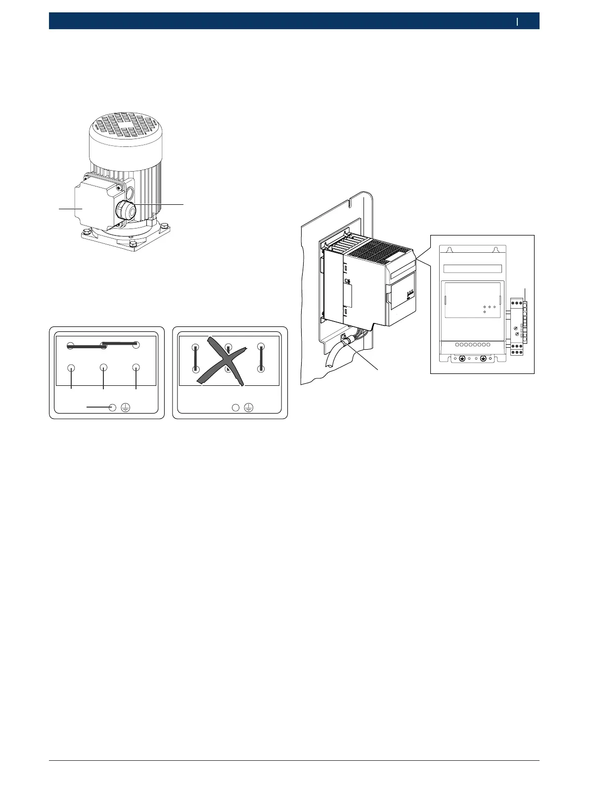
Attaching the M11 three-phase motor
i Follow the supplied circuit diagram 1 689 911 487.
1
2
Fig. 114: Three-phase motor M11
1. Draw the end of the connection cable 1 684 465 810
with the eyelets through the cable gland
(Fig. 114, item 2) into the motor terminal box.
U2
V2
W2
U1 V1 W1
U2
V2
W2
U1 V1 W1
3*2*
1*
GN/YE*
Fig. 115: Connection diagram
1*, 2*, 3*, GN/YE* are wire designations
2. Connect wires 1 to 3 and the protective conductor
(GN/YE) of the connection cable 1 684 465 810 in
the motor terminal box (see Fig. 115).
3. Attach the cover of the motor terminal box.
4. Tighten the union nut of the cable gland
(Fig. 114, item 2).
5. Insert the connection cable 1 684 465 810 through
the sealing gasket and the gasket opening into the
electric compartment
(see cable installation in Fig. 105, item 4).
! If cables U/T1, V/T2 and W/T3 are attached at the
wrong points, the three-phase motor will run in-
correctly, and the pump will accumulate little to no
pressure.
6. Attach connecting cable 1 684 465 810 of the
three-phase motor M1 to the power terminals of the
frequency converter A13 as follows:
$ Wire 1 to terminal U
$ Wire 2 to terminal V
$ Wire 3 to terminal W
458859-17_Pal
Range
Time
10s
1
2
1
RUN FWDREV
POWER
Fig. 116: Attachingand connecting connecting cable
1684465810
7. Connect the wire GN/YE of connecting cable
1684465810 to the protective conductor terminal
(see Fig. 116, item 2).
8. Connect the shielding of the connecting cable
1 684 465 810 to the adapter plate of the frequency
converter A13. To do this, attach the securing clip
(Fig. 116, item 1)to the adapter plate in the area
where the sheathing of the connectingcable
1 684 465 810has been stripped.
9. Lightly squeeze the securing clip (Fig. 116, item 1)
to provide a better contact and strain relief.