1 689 975 233 2018-05-08| Robert Bosch GmbH
64 | EPS 708 | Repairen
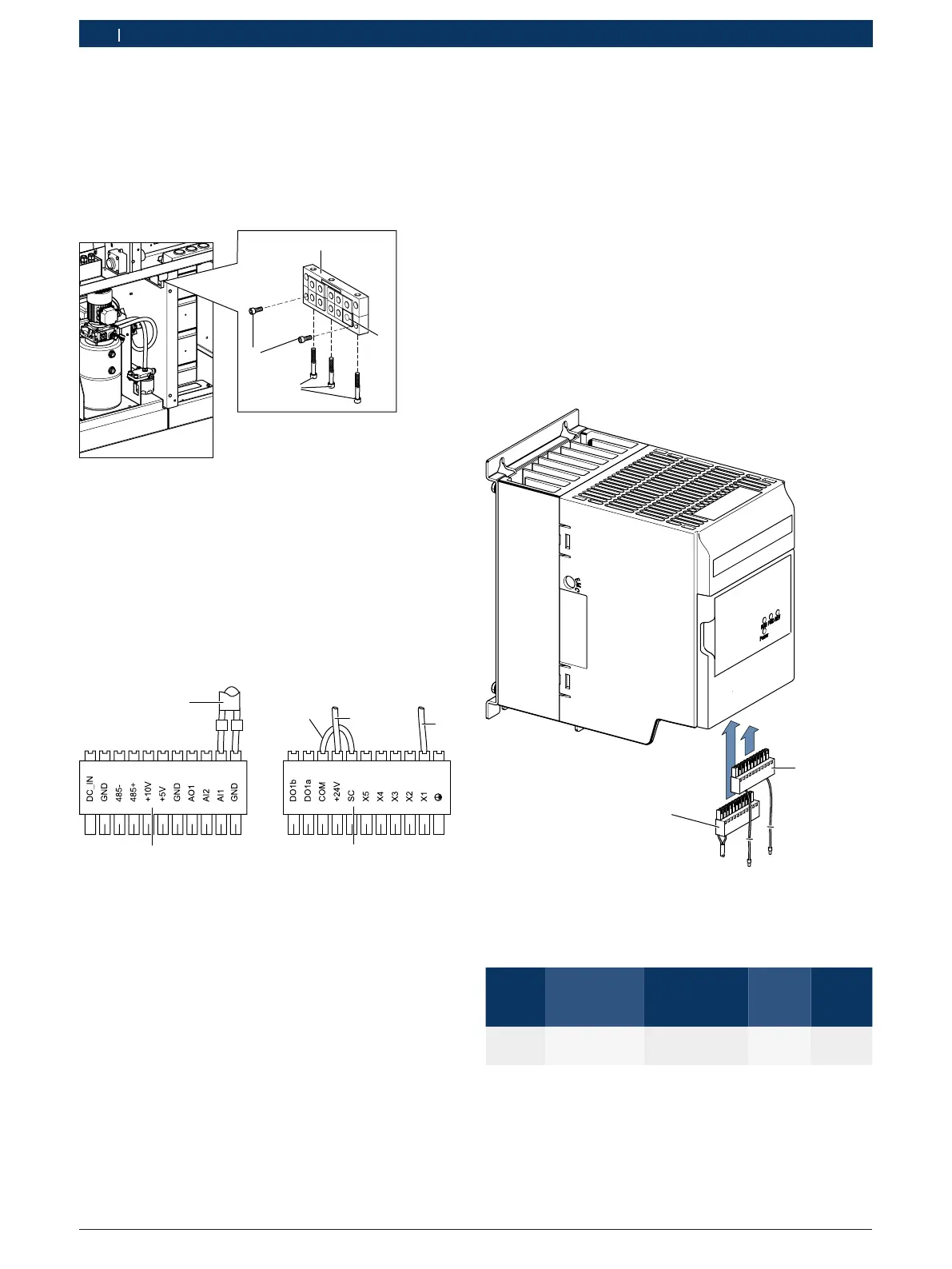
10. Pull the grommet included in the scope of delivery
over the connection cable 1684465810.
11. Insert the grommet with connecting cable
1684465 810 into the sealing gasket at position2
(see Fig. 117).
12. Reassemble and attach the sealing gasket
(see Fig. 117).
4
2
1
3
Fig. 117: Sealing gasket
Connecting the frequency converter
i Follow the supplied circuit diagram 1 689 911 487.
i The two control terminal connectors
(Fig. 118, item 1 and 2) for connecting to the control
terminals of the frequency converter are included in
the scope of delivery of the frequency converter.
458859-14_Pal
+
1
3
-
2
6
5
4
Fig. 118: Control terminal connector
i The connecting cable 1 684 463 713 (see Fig. 105)
connects the frequency converter (terminals AI1 and
GND) to circuit board A4 (terminal X263).
1. Attach connecting cable 1 684 463 713
(Fig. 118, item 3) to the control terminal connector
(Fig. 118, item 1) as follows:
$ Wire (—) to terminal GND
$ Wire (+) to terminal AI1.
2. Insert the control terminal connector from below to
the rear control terminal of the frequency converter
(see Fig. 119, item 1).
3. Connect to each other the COM and SC ports of the
control terminal connector (Fig. 118, item 2) with a
single-core cable
(Fig. 118, item 4; length = 100mm).
4. Connect the single-core cable (Fig. 118, item 5;
length=400mm) to the +24V port of the control
terminal connector (Fig. 118, item 2).
5. Connect the single-core cable
(Fig. 118, item 6; length=200mm) to the X1 port
of the control terminal connector (Fig. 118, item 2).
6. Insert the control terminal connector from below to
the front control terminal of the frequency converter
(see Fig. 119, item 2).
1
2
458859-15_Pal
Fig. 119: Port of the control terminal
7. Connect the control terminal (Fig. 119, item 2)as
follows:
L/mm From
Device/termi-
nal
To
Device/termi-
nal
Color mm²
400 A13/+24V K9/15 DBU 0.5
250 A13/X1 K9/18 DBU 0.5