1 689 975 233 2018-05-08| Robert Bosch GmbH
Repair | EPS 708 | 65 en
8. Attach further wiring as follows:
L/mm From
Device/terminal
To
Device/terminal
Color mm²
1100
*)
A13/L1 K8/2 BK 2.5
1100
*)
A13/L2 K8/4 BK 2.5
1100
*)
A13/L3 K8/6 BK 2.5
900
*)
K8/1 F6/1 BK 2.5
900
*)
K8/3 F6/3 BK 2.5
900
*)
K8/5 F6/5 BK 2.5
700
*)
K8/A1 K9/A1 DBU 0.75
700
*)
K8/A2 K9/A2 DBU 0.75
*)
The size of the cable end ferrules differ. Note the installation
position.
458859-20_Pal
F2 F3 F4 F5 F6 F7
T2
K4 K7 K8
F9
K3K2
F1
L2L1L3L2L1L3L2L1
L2 L3 L1 L2 L3 L1 L2 L3
L3L2L1L3L2L1L3L2L1L3L2L1
L1 L2 L3 L1 L2 L3 L1 L2 L3 L1 L2 L3
G4
M2
15531166742
1 L11 L11 L11 L1
DILMC7-01DIL MC7-01DIL MC7-01
A1 A1 A1 A1
A2 A2 A2
21 NC21 NC21 NC21 NC
22 NC22 NC22 NC
5 L35 L35 L35 L3
6 T36 T36 T3
3 L23 L23 L23 L2
4 T22 T12 T12 T1 4 T24 T2
PE L3L2L1
F2 F3 F4 F5 F6 F7F1
A13
X1.3
G3
L2 L3L1
I<
In
13 14 DC
18-29.5V
DC ok
Boost
ok
Signal
Input 3AC 400-500V Output DC 24V 20A
PE
LineNetz
380-440Vac
L3L2L1
Adj.
15...17V
DILMC7-01
A222 NC6 T34 T22 T1
1 L1 A121 NC5 L33 L2
A222 NC6 T34 T22 T1
Range
Time
1s
3
1
2
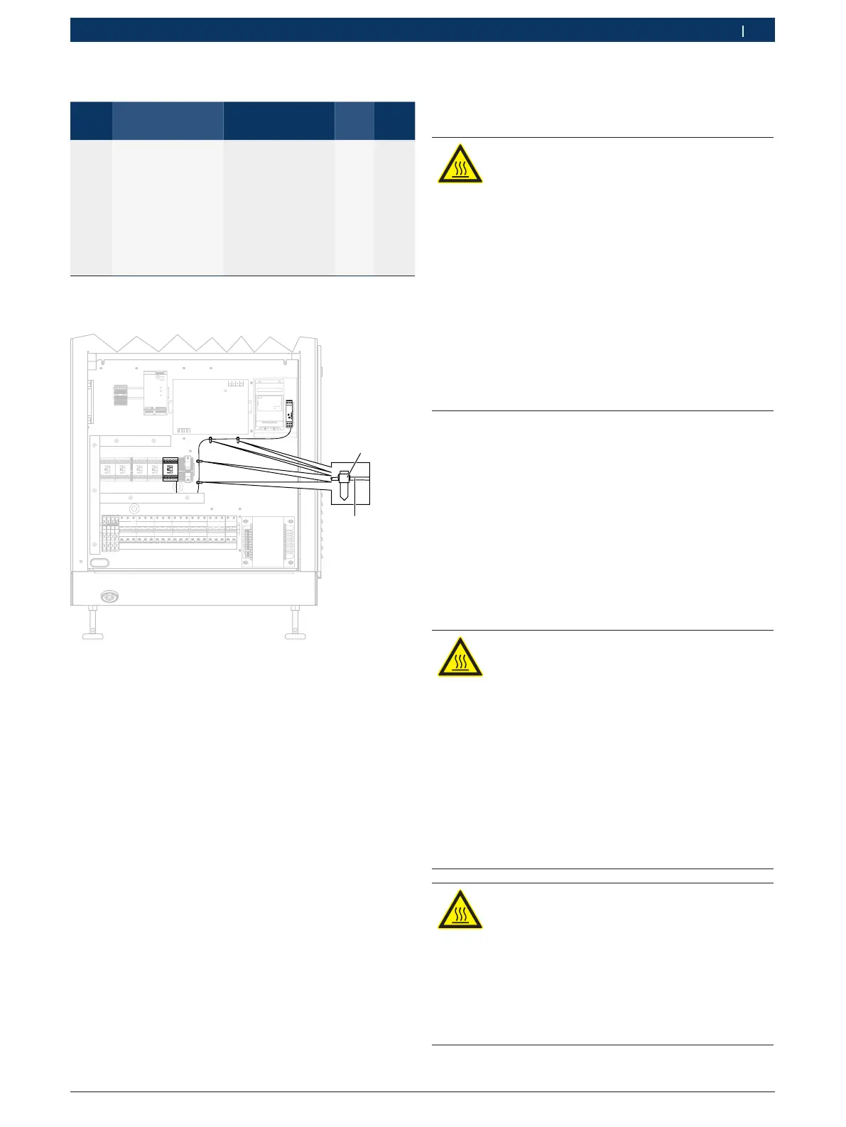
Fig. 120: Attachment points
9. Use four cable ties (Fig. 120, item 1) to attach the
single-core cable (Fig. 120, item 2), which connects
K8/A2 and K9/A2 to each other, to the mounting
panel.
10. Run all the remaining cables in the cable ducts and
close the ducts.
11. Perform safety checks in accordance with national
legislation (e.g. DIN VDE 0701-0702 in Germany).
12. Attach all of the covers to the EPS 708.
6.31.2 Changing the frequency converter
1 687 023 774 (A13)
Preparation
DANGER - Risk of electric shock from dan-
gerous voltage!
Electric shocks resulting from contact with
live parts (e.g. main switch, printed circuit
boards) can cause injury, heart failure and
fatality.
¶ Work on electrical systems or equipment
must only be performed by qualified elec-
tricians or trained personnel under the
guidance and supervision of an electrici-
an.
¶ Secure the main switch so that it cannot
be switched back on.
¶ Unplug the mains plug or disconnect the
EPS 708 from the mains before opening.
1. Switch off the EPS 708 at the main switch.
2. Secure the main switch so that it cannot be swit-
ched back on.
3. Unplug the mains plug or disconnect from mains
electricity.
4. Remove the side cover for the electric compartment
(see Fig. 6, item4).
5. Check that there is no power.
Disconnecting the supply lines for frequency conver-
ter A13
DANGER - Risk of electric shock from dan-
gerous voltage!
Electric shocks resulting from contact with
live parts (e.g. main switch, printed circuit
boards) can cause injury, heart failure and
fatality.
¶ After switching off the unit, wait 5 minu-
tes to allow the charged capacitors in the
frequency converter to discharge.
¶ Before starting to work, measure the
electrical voltage at live components to
ensure that the frequency converter can
be touched safely.
WARNING – Risk of burns from hot sur-
faces!
Touching the hot frequency converter
(>60 °C) poses the risk of burns.
¶ Do not touch the frequency converter
without wearing gloves.
¶ If the frequency converter is hot, wait 15
minutes until it has cooled down.