1 689 979 672 2012-06-26| Robert Bosch GmbH
Initial start-up | EPS 807 / 815 | �5 en
4.� Mains connection
DANGER: Risk of electric shock from live
parts
Even when the master switch is off, the input
terminals of the master switch L1, L2, L3 are
live. Contact with the input terminals of the
master switch L1, L2, L3 will lead to electric
shocks, heart failure and fatal injury.
¶ Work in the switch cabinet is only to be
performed by qualified electricians or au-
thorized personnel under the supervision
of a qualified electrician.
¶ Cover or cordon off live parts.
458735/21P
1
2
3
4
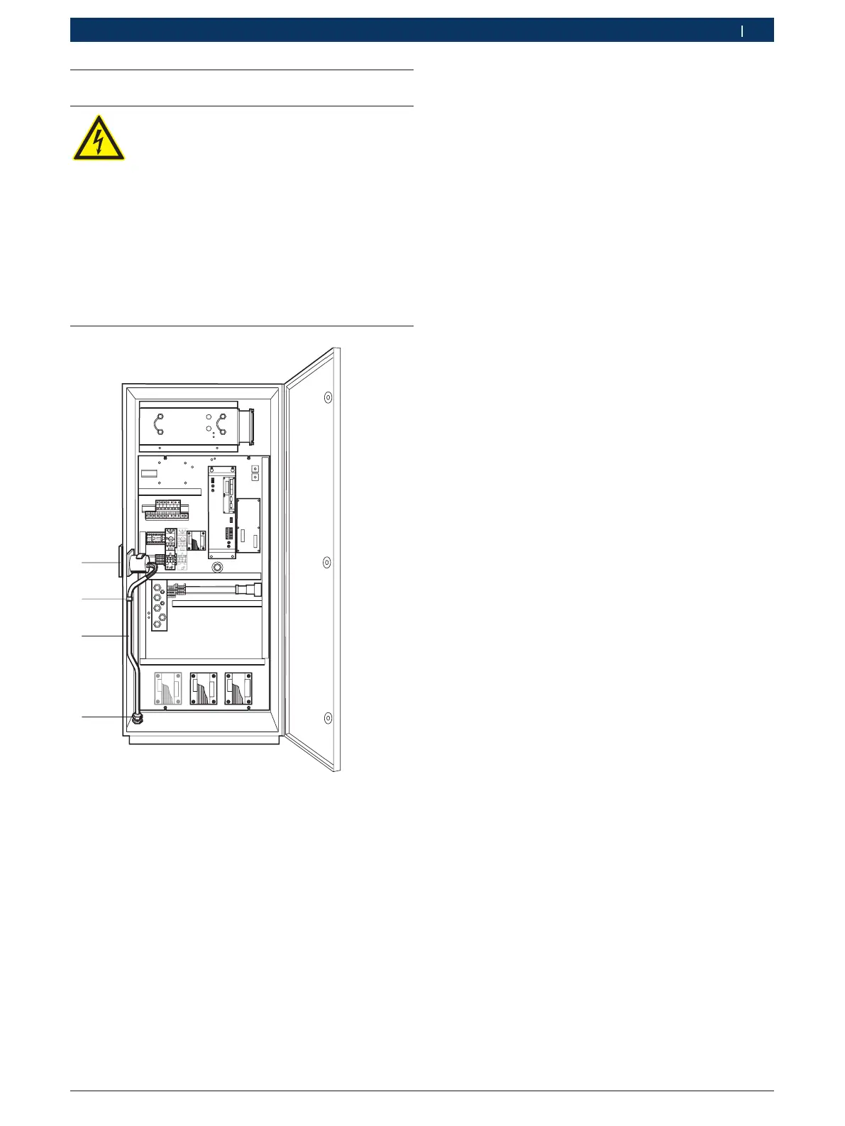
i Install the mains connection in accordance with the
enclosed circuit diagram.
The mains supply cable (3) is fed through the cable bush-
ing (4), located under the control cabinet, to the main
switch (1) and is attached to a pre-installed cable clip (2).
Please note:
The basic injection-pump test bench is always delivered
with the voltage set to the highest value:
R Basic model...001 (400 V)
$ no adjustment required
R Model...002
(200 V / 220 V / 230 V / 240 V) set to 240 V
$ adjustment required
R Model...003
(440 V / 460 V / 480 V / 500 V) set to 500 V
$ adjustment required
Adjust to the local voltage according to the enclosed
circuit diagram.
The test stand may only be connected to a grounded
symmetrical three-phase AC system at the preset local
voltage ±10% and a rated frequency of 50/60 Hz.
The protective conductor wire must have a cross-sec-
tion of at least 10 mm².
i If the MGT measuring system and a 60 Hz mains
frequency are used, the jumper on the terminal strip
in the controll cabinet must run from 161 – 162 to
163 – 163 (see wiring diagram, Pages 5).
 Loading...