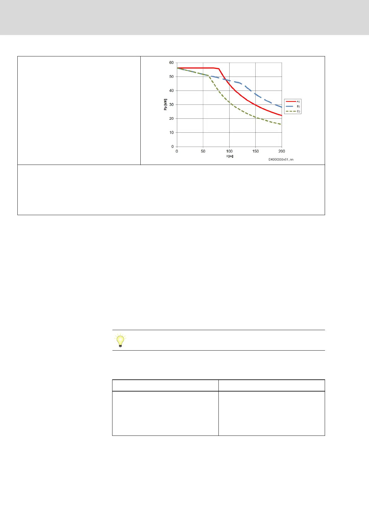
DC 750 V
Data used for the diagrams:
● Maximum peak current of 3 × I
Bypass
: 75 A
● Threshold of braking resistor in supply unit or converter: 820 V
See also "P-0-0833, Braking resistor threshold"
See also "P-0-0860, Converter configuration"
A) Peak power when decelerating
B) Peak power when accelerating (n < 0.8 × n
eck
; n
eck
: speed at
which the torque characteristic is inflected)
C) Peak power when accelerating (n < 0.9 × n
eck
; n
eck
: speed at
which the torque characteristic is inflected)
P
P
Maximum peak power (sum of all P
DC_max
in the drive line)
l
total
Sum of the lengths of all hybrid cables at a KCU
Tab. 7-2: Available Peak Power vs. Cable Length for DC 500 V and DC 750 V
Peak power when accelerating
Due to voltage drops, less peak power is available at KSM/KMS with
increasing length of the motor cable. During acceleration, this becomes
noticeable by the reduction of the corner speed. The figure shows exemplary
curves of reduction to 80% and 90% of the data sheet corner speeds. The
maximum speed is proportional to the DC bus voltage available at the motor.
In the drive line, place the KSM/KMS with the greatest power as
near as possible to the output of KCU.
Examples (cable length: 100 m)
565 V DC 750 V DC
● Motive: 32 kW at most
● Regenerative: 45 kW at most
● With 18 kW, a maximum speed of
approx. 90% of the corner speed
can be reached.
● Motive: 47 kW at most
● Regenerative: 45 kW at most
● With 32 kW, a maximum speed of
approx. 90% of the corner speed
can be reached in motive form.
Tab. 7-3: Examples
224/407
Notes on project planning
IndraDrive Mi Drive Systems with KCU02, KSM02,
KMS02/03, KMV03, KNK03, KLC03
Bosch Rexroth AG R911335703_Edition 04