264
POWERHEAD
INSTALLATION
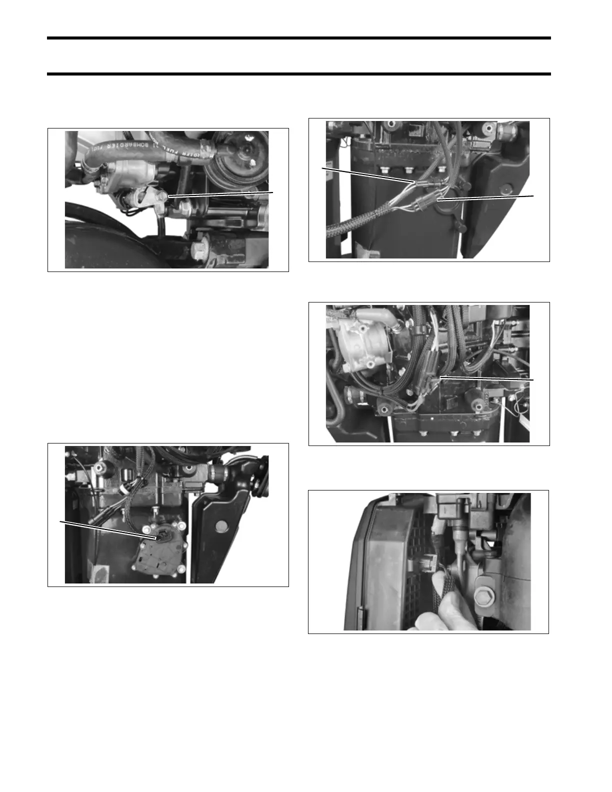
Position the shift rod in the shift rod lever. Install
the retaining screw and washer. Torque screw to
60 to 84 in. lbs. (7 to 9.5 N·m).
IMPORTANT: Confirm that gearcase shifts sol-
idly into both forward and reverse and that propel-
ler shaft spins freely in neutral.
V4 MODELS
Fill exhaust valve actuator electrical connector
with Electrical Grease and install on actuator.
IMPORTANT: Leave enough slack in harness
so that lower cover will not pull it away from actua-
tor.
ALL MODELS
Connect the power trim connectors.
Install air silencer and air temperature sensor.
1. Shift rod screw 005253
1. Actuator connector 005247
1
1
1. Tilt limit switch connector
2. Sending unit connector
005254
1. Tilt relay connector 005255
005272
2
1
1