EasyManua.ls Logo

Burkert 8175 - User Manual

Burkert 8175
66 pages
Print Icon
To Next Page IconTo Next Page
Loading...
TYPES 8175 / 8170
ULTRASONIC LEVEL TRANSMITTER
COMPACT AND SEPARATE VERSIONS
Instruction Manual Ident. 427998P

Questions and Answers

  • J
    Joseph SmithSep 10, 2025
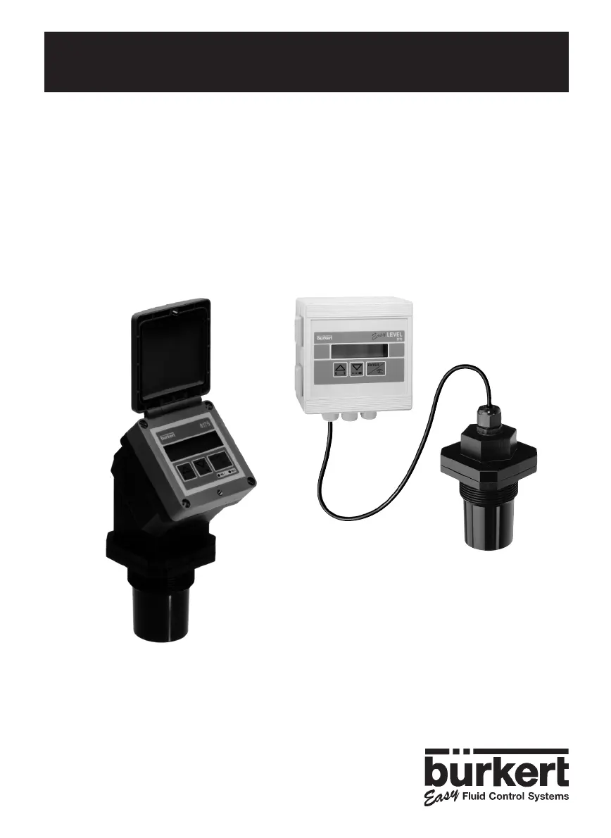
    What does a blinking display on a Burkert Transmitter mean?
    • R
      Ronald CarrilloSep 10, 2025
      A blinking display on your Burkert Transmitter suggests a potential issue. Try performing an echo reset. Also, check the connection of the connectors to ensure they are properly seated.
  • E
    Emma HaysSep 12, 2025
    What causes a current output of 22 mA on a Burkert 8175 Transmitter?
    • M
      millerkristiSep 12, 2025
      A current output of 22 mA on your Burkert Transmitter can be due to several reasons. It can be caused by the device being out of range, in this case, see above for solution. If the display is blinking, re-calibrate the device. If the display message is 'ERROR', see above for solution.
  • A
    Alexandra CarlsonSep 14, 2025
    How to fix Burkert 8175 programming unavailable issue?
    • J
      Joshua JordanSep 14, 2025
      If programming is unavailable on your Burkert Transmitter, set the SW1 switch to the right.
  • B
    Bryan FarrellSep 16, 2025
    How do I resolve a fixed current output value (4 or 20 mA) on a Burkert Transmitter?
    • A
      Adam ZunigaSep 16, 2025
      If you have a fixed current output value (4 or 20 mA) on your Burkert Transmitter, program the current output.

Summary

1 INTRODUCTION

1.2 General Safety Instructions

Provides essential safety guidelines for product installation and use.

2 QUICKSTART

2.1 Installation

Guide to installing the 8175 Level Transmitter.

2.2 Programming

Guide to programming the 8175 Level Transmitter.

3 INSTALLATION

3.1 General Installation Guidelines

General advice for installing the 8175 ultrasonic level transmitter.

3.2 INSTALLATION

3.2.1 PANEL VERSION INSTALLATION

3.2.2 WALL-MOUNTED VERSION INSTALLATION

3.4 GENERAL ELECTRICAL CONNECTION

3.4.1 WIRING VIA A CABLE PLUG

Details on wiring the 18-32 VDC version using a cable plug.

3.4.2 8175 COMPACT VERSION, 18-32 VDC, WITH PG 13.5

8175 COMPACT VERSION, 115;230 VAC

3.4.3 8175 PANEL VERSION 18-32 VDC

8175 PANEL VERSION 18-32 VDC, WIRING

Wiring diagrams for the panel version, 18-32 VDC.

3.4.4 8175 WALL MOUNTED VERSION 18-32 VDC

3.4.4 8175 WALL MOUNTED VERSION, 18-32 VDC; WIRING

4 OPERATION

4.1 OPERATING AND CONTROL GUIDE

Explains the LCD display and key functions.

4.2 MENU GUIDE

4.4 CALIBRATION MENU

4.4.3 FILTER FUNCTION

4.4.4 GAS CHARACTERISTICS

4.4.5 ECHO FILTERING

4.4.6 TEACH-IN PROCEDURES

4.4.6.1 TEACH-IN FOR LEVEL AND DISTANCE

Defines relationship between transmitter and fluid by distance or level.

4.4.6.2 TEACH-IN FOR VOLUME

D - MANUAL INPUT OF DISTANCES AND ASSOCIATED VOLUMES

E - VOLUME TEACH-IN PROCEDURE

4.4.7 OUTPUT CURRENT

4.4.8 RELAY (OPTION)

4.5 TEST MENU

4.5.1 OFFSET COMPENSATION

4.5.2 SPAN COMPENSATION

4.5.6 RESETTING OF THE TRANSMITTER

5 MAINTENANCE

5.2 TROUBLE SHOOTING GUIDE

Assists with problems during installation or operation.

5.2 TROUBLE SHOOTING GUIDE (CONTINUED)

6 SPECIFICATIONS

6.1 SPECIFICATIONS (CONTINUED)

6.4 DESIGN AND MEASURING PRINCIPLE

Burkert 8175 Specifications

General IconGeneral
BrandBurkert
Model8175
CategoryTransmitter
LanguageEnglish

Related product manuals