Table 2: DynaMax Wall Hung Service Clearances
Model
Service Clearance, Inches (cm)
Front Top Right Side Left Side Rear
80
24” (61cm) 3” (8 cm) 4” (10 cm) 4” (10 cm) 0” (0 cm)
100
24” (61cm) 3” (8 cm) 4” (10 cm) 4” (10 cm) 0” (0 cm)
150
24” (61cm) 3” (8 cm) 4” (10 cm) 4” (10 cm) 0” (0 cm)
200
24” (61cm) 3” (8 cm) 4” (10 cm) 4” (10 cm) 0” (0 cm)
250
24” (61cm) 3” (8 cm) 4” (10 cm) 4” (10 cm) 0” (0 cm)
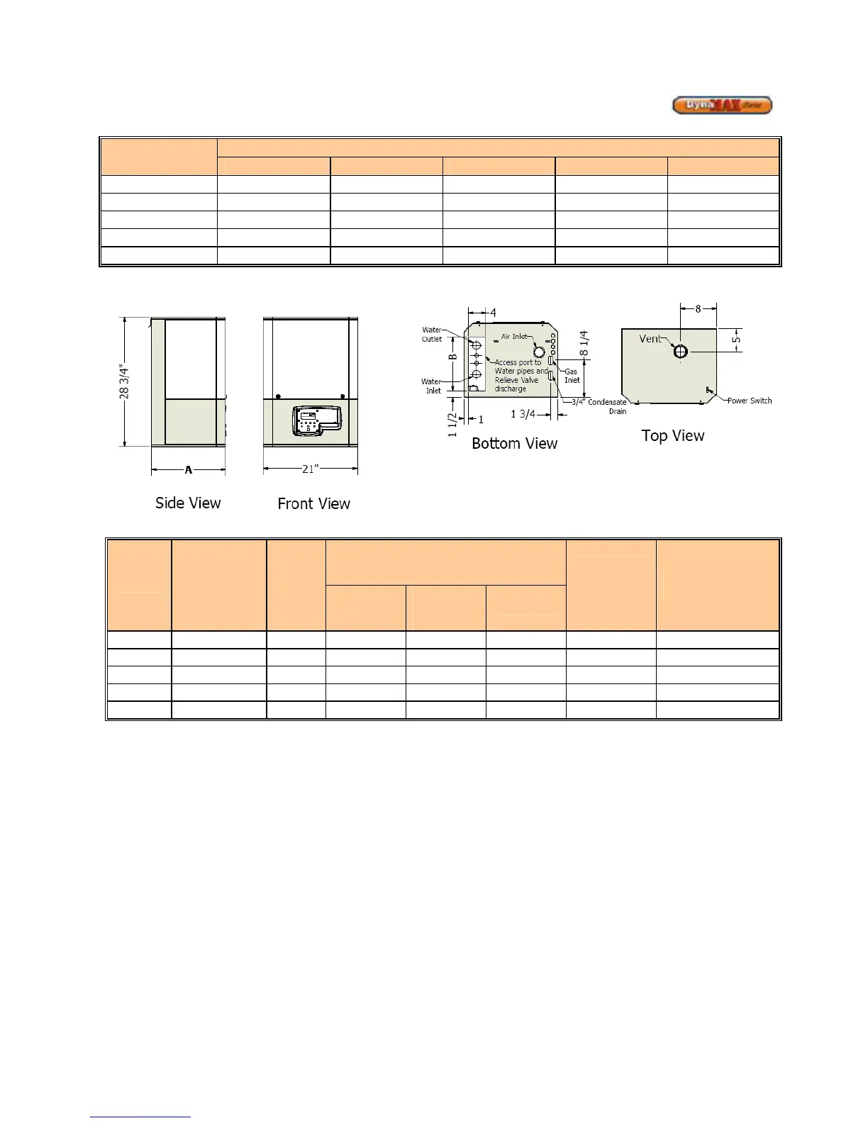
Figure 3: DynaMax Wall Hung Model Dimensions
Table 3: Appliance Dimensions and Specifications
Model
Depth Dim.
"A" [in.]
Dim.
"B"
[in.]
250
23 1/2 19 3 3 2 1 1/4 1/2
Maintain minimum specified clearances for adequate operation. All installations must allow sufficient space for servicing the vent
connections, water pipe connections, circulating pump, bypass piping and other auxiliary equipment, as well as the appliance