PART 7 COMPONENTS
7.1 DIRECT SPARK IGNITER
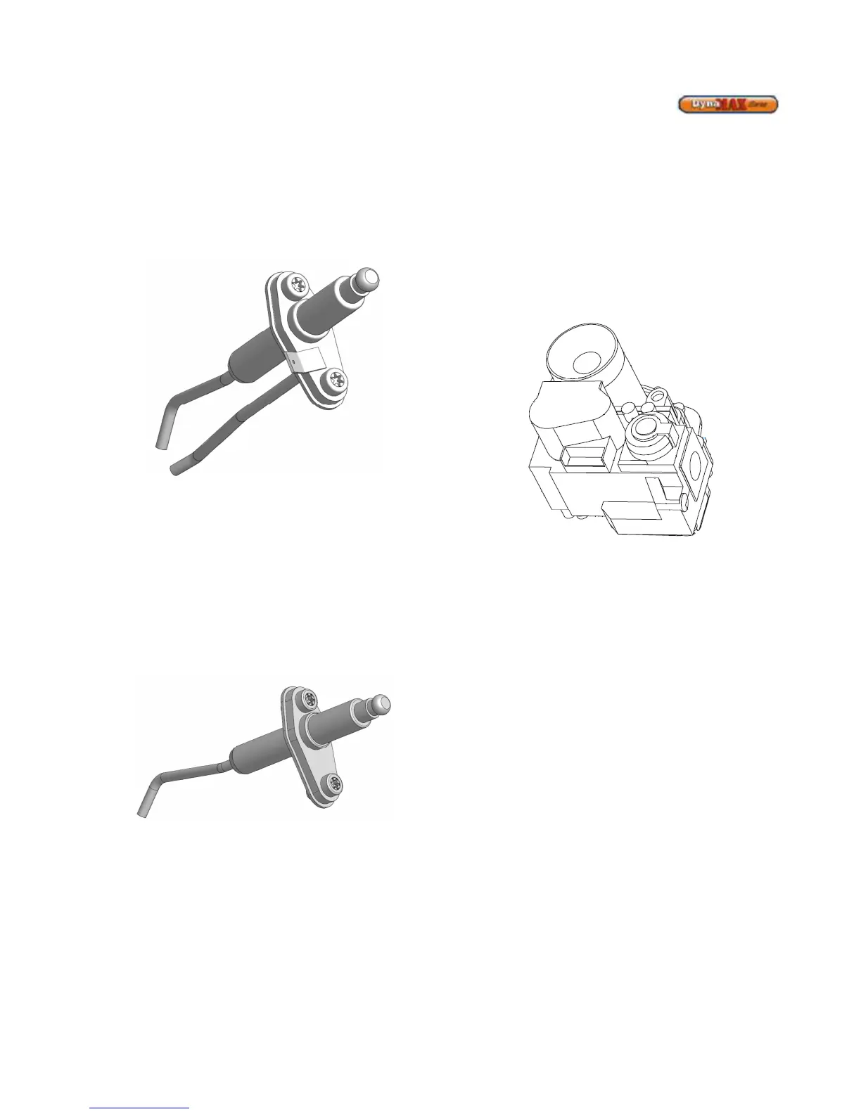
The direct spark igniter is inserted directly through the
combustion chamber front door and held in place by two
torx-20 screws. Care must be taken when removing and/or
installing the igniter. Always remove the igniter prior to
removing the fan assembly for inspection of the burner and
heat exchanger.
Figure 23: Direct Spark Igniter
During a trial for ignition sequence a properly operating
igniter will generate a continuous spark with a 9/64” (3.6mm)
spark gap. It is recommended to clean the direct spark
igniter using steel wool as required. DO NOT use sandpaper
or grit-cloth since this will contaminate the metal surface.
7.2
FLAME SENSOR
The flame sensor is inserted directly through the combustion
chamber front door and is screwed into the combustion
chamber front door by torx-20 screws. Care must be taken,
when installing the flame sensor, to align it perpendicular to
the fan flange and parallel to the burner tube and not to over
tighten.
Figure 24: Flame Sensor
The ignition module relies on the flame sensor to provide a
flame rectification signal. Oxide deposits, improper
placement or damaged ceramic insulator will result in
insufficient signal leading to ignition module lock out. For
proper operation minimum 1.25 µA DC must be fed back to
the module. Oxide deposit on the sensor rod must be
removed with steel-wool. DO NOT use sand-paper or grit-
cloth since this will contaminate the metal surface.
7.3 COMBUSTION AIR FAN
DynaMax uses a modulating air fan to provide combustible
air/gas mix to the burner and push the products of
combustion through the heat exchanger and venting system.
The fan assembly consists of a sealed housing and fan
wheel constructed from spark resistant cast aluminum. The
fan is operated by a fully enclosed 120 VAC, Single-Phase
EC/DC electric motor. The fan housing and motor assembly
is fully sealed and SHOULD NOT be field serviced. The
power draw of the motor is proportional to the modulated gas
input rate of the appliance.
7.4 GAS VALVE
Figure 25: Venturi and Gas Valve Arrangement
The Gas Valve supplied with the DynaMax boiler is a
combined valve/venturi assembly. A servo pressure
regulator is incorporated into the gas valve to provide stable
gas supply. Pressure taps are provided to check inlet and
outlet gas pressures. An internal fine mesh screen is
incorporated in the inlet of the gas valve to prevent debris
from entering the combustion chamber. Gas valves are
factory set at low and high fire and modulates to maintain
combustion characteristics across the full operating range.
7.5 OUTER JACKET
The outer jacket assembly is constructed from mirror finish
stainless steel. This ensures a long life for the jacket
assembly, with full integrity