IMPORTANT
Upon completion of initial installation or following any repair
work on the gas system, leak test all gas connections with a
soap solution while the main burner is firing. Immediately
repair any leak found in the gas train or related components.
DO NOT operate an appliance with a leak in the gas train,
valves or related gas piping.
3.5 HIGH and LOW GAS PRESSURE SWITCHES
(Optional)
High and low gas pressure switches are available as an
option and are wired in series with the normally closed
blocked flue switch. The high gas pressure switch is used to
monitor the differential gas pressure between the outlet of
the control valve and the fan inlet. If differential gas pressure
exceeds the maximum setting of the pressure switch, the
appliance will shut down and a Blocked Flue Error will be
indicated on the display panel. The low gas pressure switch
is to monitor the minimum incoming gas supply pressure
supplied to the gas train. If gas pressure falls below the
minimum setting of the pressure switch, the appliance will
shut down and a Blocked Flue error will be displayed.
3.6 AIR/GAS RATIO VALVE
The main gas valve supplying gas to the burner on this
appliance utilizes a servo pressure regulator providing a
slow opening, fast closing safety shut off and air/gas ratio
control for the gas combustion process. The valve is a 1:1
negative pressure gas valve. The valve performs the
functions of a pressure regulator, safety shutoff, and air/gas
ratio control. Full closing of the valve seat occurs in less than
0.8 seconds when the valve is de-energized. Operation of
the gas valve in combination with the combustion air fan
allows the burner input rate to vary from 20% to 100% based
on temperature demand. The inlet gas supply pressure must
be maintained within the specified minimum and maximum
pressures as indicated in Table 9.
The air/gas ratio is preset at the factory and adjustment is
not usually required if gas supply pressure is maintained
within the specified range. There are no serviceable parts on
the air/gas ratio valve control.
Figure 14: DynaMax 80 – 250, 260 1:1 Air/Gas Ratio
Control Valve
Figure 15: DynaMax 299 – 399 1:1 Air/Gas Ratio Control
Valve
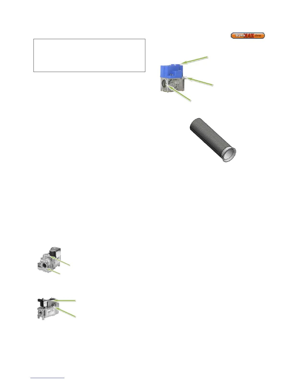
Figure 16: DynaMax 500 – 800 1:1 Air/Gas Ratio Control
Valve
3.7 BURNER
Figure 17: DynaMax Burner
This appliance uses a single cylindrical burner installed
horizontally into the cavity located in the center of the heat
exchanger. A unique burner is used for each one of the
DynaMax models.
Burners may NOT be interchanged between different Btu/hr
input models. The burner consists of a round mounting
flange welded to a ported stainless steel mixing tube. This
stainless steel tube is covered with a close fitting, knitted
stainless steel metal fiber alloy material that forms the burner
outer surface. The burner is setup to operate in blue mode
and infrared operating condition should be avoided. Infrared
operation will occur only if air to gas adjustments is incorrect.
If infrared operation is noted the cause must be corrected.
The burner should be removed for inspection and cleaning
on an annual basis. An appliance installed in a dust or dirt
contaminated environment will require inspection and
cleaning on a more frequent schedule. The fan assisted
combustion process may force airborne dust and dirt
contaminants, contained in the combustion air, into the
burner. With sustained operation, non-combustible
contaminants may reduce burner surface area, reduce
burner input or cause non-warrantable damage to the
burner.
Airborne contaminants such as dust, dirt, concrete dust or
dry wall dust can be drawn into the burner with the
combustion air and block the burner surface area. DO NOT
operate this appliance during construction.
The spark igniter and flame sensor are removable from the
combustion chamber mounting door without removing the
burner assembly.
Never use an open flame (match, lighter, etc.) to check
gas connections.
Low-fire air/gas ratio
adjustment, use slotted
screwdriver for adjustment,
clockwise increases CO
2