12.15 Alarm Output (if equipped)
This is a feature that is offered on the 848IF. An alarm output
is available to signal was sensed in the connected heating
system. Once an alarm is signalled by the alarm output it
can be reset by means of the External Reset Input.
The alarm output is a normally open, dry contact/ potential
free output. If an error is sensed in one of the attached
boilers the Alarm output contact closes. The output can be
used to drive an external device such as a lamp, a buzzer, a
PLC or a building management system. Refer to 15.3 848IF
Interface Module Wiring Schematic for complete wiring
details.
The IF code scans its Modbus holding registers (0x0000,
0x0010...0x0090) for a STATE that is not equal to zero. If a
state not equal to 0 (zero) is found the IF subsequently
checks for an ERROR_NUMBER not equal to 0xFF to see if
this device is in error. If so, the alarm relay is energized and
the alarm output contact closes.
The alarm output functionality can be used even if Modbus
communication is non-existent.
Due to communication latency it can take several minutes for
the Alarm output to reflect the state of any of the connected
boilers. Especially in a cascade system and/or when
LabVision is connected.
12.16 External Reset (if equipped)
The external reset can be controlled by a relay or
pushbutton.
If the input is open the resetting of an error is an enabled.
Once an error is signalled by the alarm output it can be reset
by shorting the external reset input to 0V. A reset command
is then sent over to the DynaMax Ignition Module and the
external reset is disabled until the input is open again. Refer
to 15.3 848IF Interface Module Wiring Schematic for
complete wiring details.
12.17 0-10Vdc External Input (if equipped)
An analog input can be used to control the CH or the DHW
set point. The input can handle input voltages of up to
10Vdc. A resistor of 500Ω may be added to obtain a 0-
10Vdc input from a 4-20mA signal. Refer to 15.3 848IF
Interface Module Wiring Schematic for complete wiring
details.
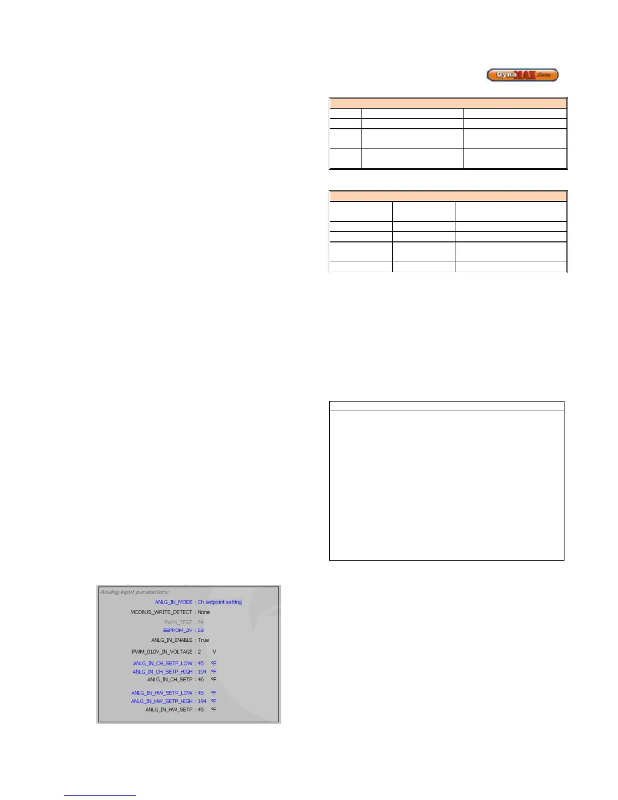
The analog input setting screen is shown below in
LabVision:
Figure 68: Analog Input Parameters
Table 42: Analog Input Selection
F
The ANLG_IN_ENABLE parameter determines whether the
analog input is enabled or disabled. The ANLG_IN_ENABLE
parameter is set to ‘False’, analog input is disabled, under
the following circumstances
• When the ANLG_IN_MODE is set to 0 (off)
• When the input voltage is less than 2V
• From the moment a Modbus write command is
detected until 4.25 minutes after the last Modbus
write command was ended. Modbus set point
setting has priority over the Analog input set point
setting
• During commissioning (and when altering the
ANLG_IN_MODE setting) the setpoint that is not
controlled by the analog (or Modbus) must be checked/
set manually after setting the mode
• If the Analog input is not connected (open) the default
input voltage is 2.5V. If the analog input is not to be
used it must be disabled by setting ANLG_IN_MODE to
0.
• The analog input and Modbus connection can be used
simultaneously but when the Modbus connection is
used to set the setpoint the analog input is disabled.
• In a cascade system only the setpoints of the MN board
connected directly to the IF board can be controlled.
12.18 APPLIANCE
∗ Remove manometers and tighten test port screws.
∗ Fill out start up report for each heater. Be sure to record
all settings and readings. Retain a copy of report for
future reference.
∗ Start up is now complete and heater may be placed into
service.