Slave Boiler
Turn on the DynaMax Slave Boiler and wait until the Date
and Time to appear.
11) Press [MENU]
12) Select “Appliance Settings” using the [NEXT]
button and press [ENTER].
13) Select “Cascade Control” using the [NEXT] button
and press [ENTER].
14) Enter the PIN Number to gain access. The numbers
can be moved up and down using the
[UP]/[DOWN] keys and press [ENTER] to move to
the next digit.
15) Select “Slave Boiler 2” using the [UP]/[DOWN]
keys and press [ENTER] to confirm.
If there are more than 2 boilers (up to 8) continue
with step 16.
If not, go to step 18.
16) Repeat steps 7-10 for the following slave boiler(s)
17) Select the next “Slave Boiler” in the sequence. The
boilers must be addressed in sequential order. That
is, the Master Boiler is addressed as 1 the first
Slave Boiler is addressed as 2, the next Slave
Boiler is addressed as 3 etc.
18) Press [MENU] until the Date and Time appear on
the home screen.
19) The home screen should read “System: S2”. The
third boiler in this series will be S3 and so on. If not,
go through steps 11-15 again.
20) Programming is complete. DO NOT turn off the
Slave Boiler.
12.13 INTERFACE MODULE (if equipped)
The DynaMax Interface Module comes complete with:
• 0-10Vdc External Input
• Alarm Output
• Modbus RTU Communication
• External Reset
Wiring Setup
Refer to Figure 66 and 67 for a pictorial description of how to
connect the Interface module.
Figure 64: Text Display Detail
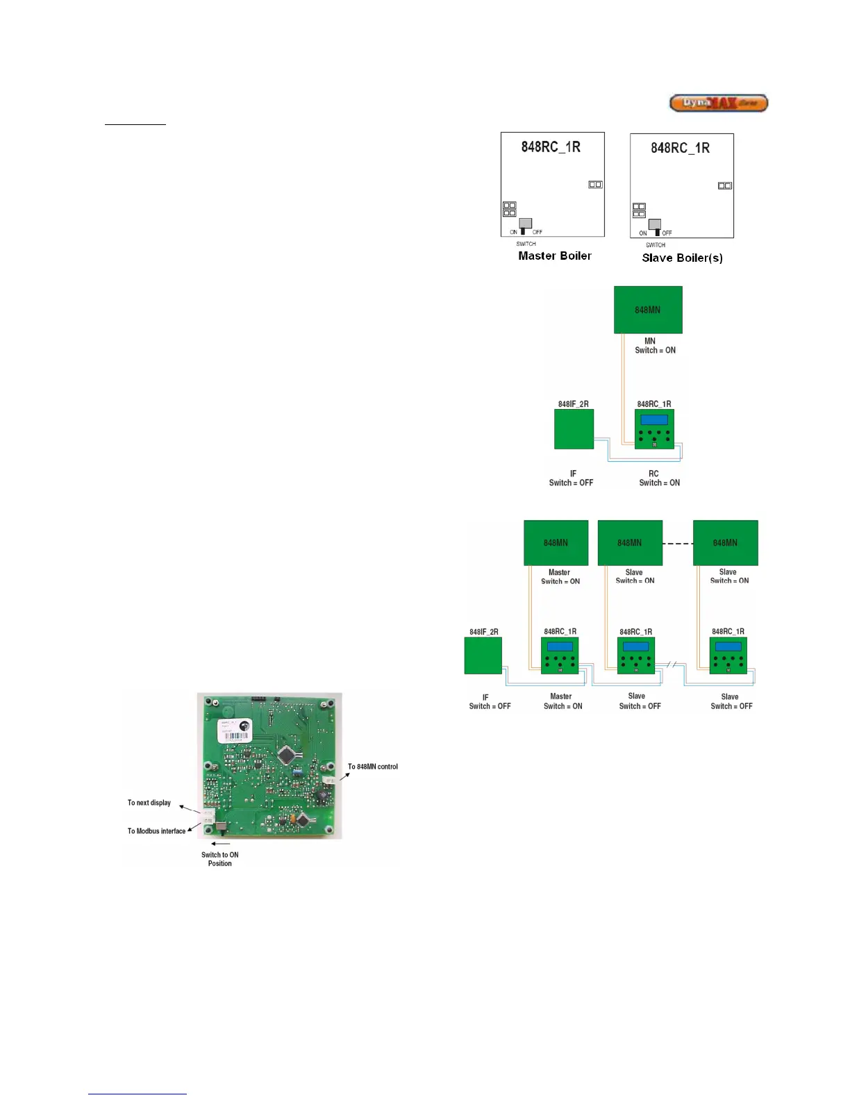
Switch Setup
There is a switch located on the backside of the text display.
Only the Master Text Display is required to provide power to
the Slave boilers, therefore the switch on the backside of the
Master display should be in the ON position, and the switch
at the Slave displays should be in the OFF position. Figure
65 refers to how the switch is to be placed.
Figure 65: Text Display Switch Setup
Figure 66: Standalone boiler with Modbus Interface
Figure 67: Cascade boilers with Modbus Interface
Modbus communicates using words (the contents of 16-bit
holding registers). The data that is offered by the 848IF is
organized as a list of bytes. Table 33 shows the parameters
available for reading and their addresses.
NOTE: The toggle switch located on the 848IF must be
pushed towards the red/white stripped wires.