DHW Priority
When both a CH demand and DHW demand exist
simultaneously, DHW will always have priority. When DHW
demand ends the boiler will check the Outlet Temperature
sensor or System Sensor and Room Thermostat switch to
determine if CH demand exists.
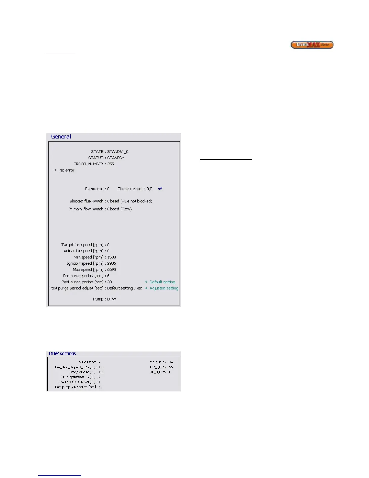
Flame rod current in µA can be observed. Fan speeds
cannot be altered here, instead they are varied under the
Settings screen. This is covered in Section 8.2 of this
manual The Maximum Stack Setpoint Temperature and the
Flue Diff. Temperature cannot be changed to preserve
reliable and efficient performance.
Figure 43: DHW Mode 4 General Screen
To change a blue coloured parameter, place the cursor over
a parameter and double-click. This will bring up a window to
enter the desired values of operation. Take note of the
minimum and maximum values that can be entered, as the
values entered MUST be within this range
Figure 44: DHW Mode = 4 Settings
8.7 LABVISION CASCADE
When connected in a cascade setup the Master boiler can
control up to 7 slave boilers (ie. a total of 8 boilers) from the
control panel of the Master Boiler. All control operation can
be performed on the Master boiler, which can then relay the
relevant information to the slave boilers. Therefore a direct
connection to the Master Boiler and LabVision is required for
communication using LabVision.
When the master boiler detects a heat demand for CH this
boiler will start and uses it own parameters for CH demand.
If after cascade_delay_time the system temperature is still
below the set point the next boiler will start.
When the master temperature (T_system) plus
cascade_hyst is greater than the set point a boiler will be
stopped. If after a period of cascade_delay_time this
situation is still present the next boiler is switched off.
Sequence of Operation:
When a boiler is set as MASTER (address =1), the controller
of this boiler will drive the cascade. THE CH mode of the
master boiler is applicable for the total cascade system.
• The outdoor temperature sensor connected to the
MASTER will be the outdoor sensor for the cascade
system
• The system temperature sensor connected to the
MASTER will be the control sensor for the cascade
supply temperature.
• The thermostat connected to the MASTER will be
the CH heat demand input for the cascade system.
When demand for CH present the first boiler will start and
uses its own parameters for CH demand. After a period of
CC_TIME the MASTER compared the system temperature
with the cascade set point and will check if:
1) An additional boiler is needed
T_system < CH set point – cc_hyst
2) Number of boilers remain the same
T_system > CH_setpoint – cc_hyst AND
T_system < CH set point + cc_hyst
3) A boiler should stop.
T_system > CH_setpoint + cc_hyst