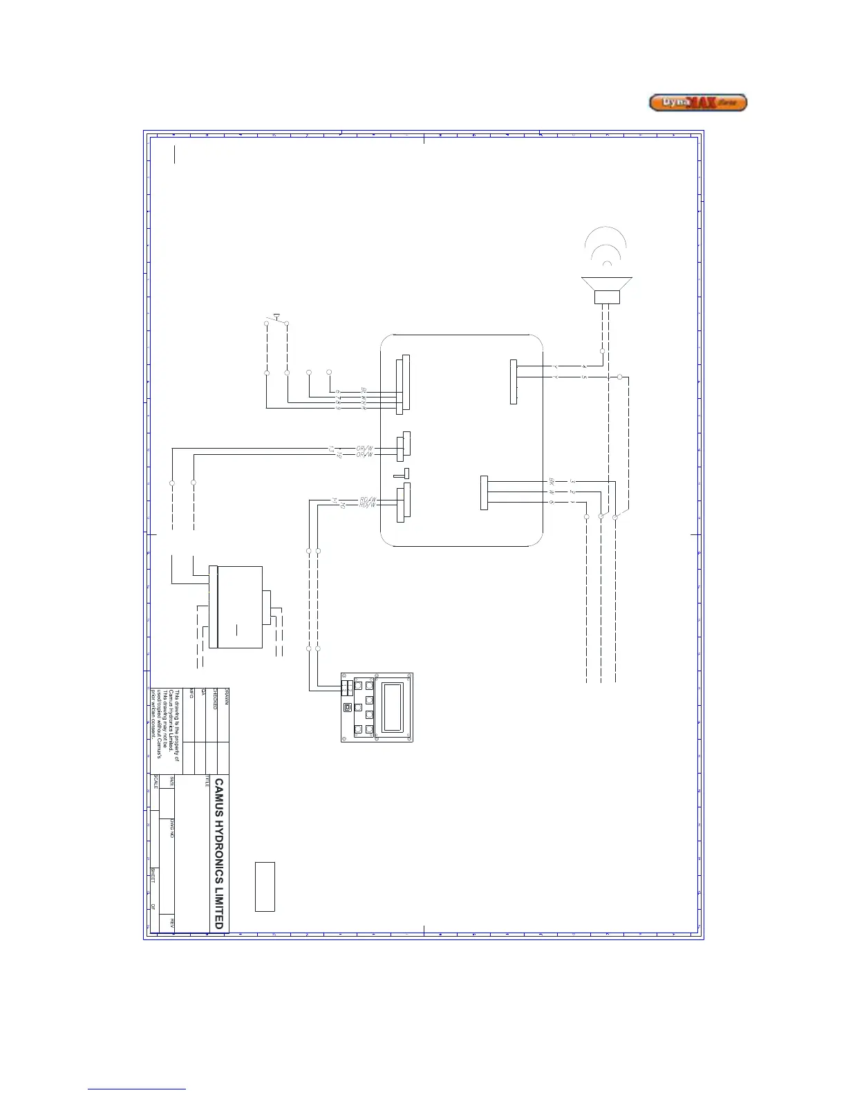
15.3 848IF Interface Module Wiring Schematic
---- FIELD SUPPLIED
····· OPTIONAL EQUIPMENT
BK - BLACK
BL- BLUE
BR - BROWN
G - GREEN
O - ORANGE
P - PURPLE
W - WHITE
Y - YELLOW
R - RED
Note: 1) If any of the original wire as supplied with the
appliance must be replaced, it must be replaced with
wiring having a temperature rating of at least 105C
CONNECTION
DIAGRAM
99-0134
1
1
01
C
KC
May-05-09
DynaMax, Interface Module (848IF),
Electrical Connection Diagram
1 2 3 4
J2
3 2 1
GROUND
L
N
115V 60Hz
FIELD SUPPLY
2 1
4 3
1 2 3
6 5 4
J1
J4
J7
5 4 3 2 1
10 9 8 7 6
J5
ALARM (24 VAC / 115 VAC)
EXTERNAL
RESET
0-10Vdc
EXTERNAL
INPUT
DISPLAY
MODBUS
COMM.
NOTE:
1) Alarm contact must be powered externally with 24Vac or 115Vac.
2) Alarm can drive an external device such as a lamp, buzzer, PLC or Buidling Management System (BMS)
DATA +
DATA -
-
+
PROTONODE
MODBUS TO
LONWORKS OR
BACNET CONVERTER
(if equipped)
+-G
CONNECT
TO BMS
+
-
G
+PWR
-PWR G
24Vac
(Field Supplied)
848IF
INTERFACE MODULE
DATA +
DATA -