The Anti_Cycle_Period is designed to prevent the boiler from
short-cycling. The preset time must be satisfied before the
boiler will start up.
8.5.2 Central Heating Mode = 1, 2, 3 Installer Level
Figure 37: Central Heating Mode = 1, 2, 3 Settings
The following parameters can be adjusted:
Table 21: CH Mode = 1 Parameters
Parameter Parameter Description
t_day_ref
When the outdoor temperature is
below the preset Weather_setpoint
a CH demand is created.
Therefore, the CH demand is not
dependent on Room Temperature
input. (Default: 68
o
F)
To change a blue coloured parameter, place the cursor over
a parameter and double-click. This will bring up a window to
enter the desired values of operation. Take note of the
minimum and maximum values that can be entered, as the
values entered MUST be within this range.
8.6 LABVISION DOMESTIC HOT WATER
Use the pull down menu and select DHW Mode 4 to adjust
parameters. Before the parameters can be adjusted the blue
status bar must track left-to-right and back again. Refer to
Section 8.1 to resolve connection issues.
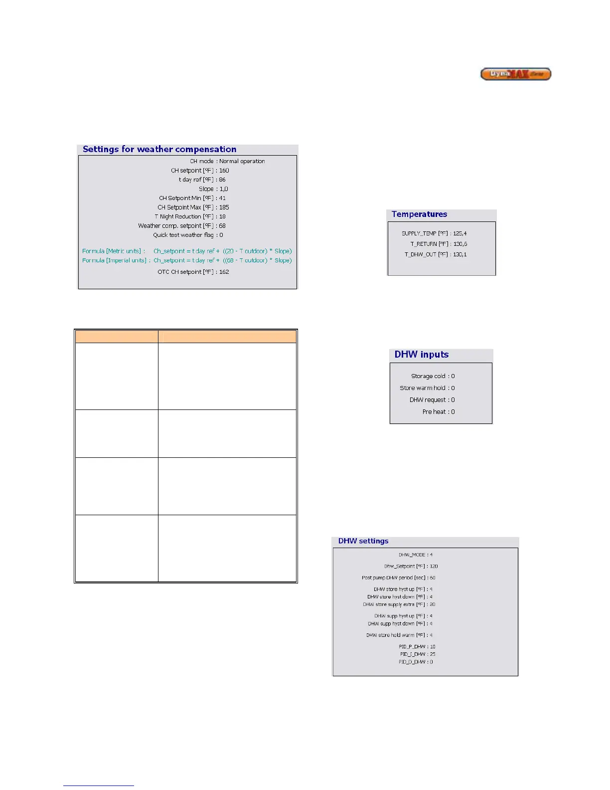
Real-time temperatures are tracked by LabVision and are
displayed on the screen. The temperatures tracked are:
• Outlet/Supply Temperature (T_SUPPLY)
• Inlet/Return Temperature (T_RETURN)
• DHW Supply Temperature (T_DHW_OUT)
Figure 38: DHW Temperature Screen
The DHW section of the screen displays the request that the
DynaMax boiler is responding to. The values for the 4
parameters: Storage cold, Tap flow, DHW request, and Pre
heat vary from 0 (off) and 1 (on). This information is also
listed under the General section as well.
Figure 39: DHW Inputs
The Pre heat and Tap flow screens are designed to keep the
DynaMax operating at its optimum setting, and therefore
these parameters will be preset and cannot be changed.
8.6.1 DHW Mode = 0, Installer Level
No parameter changes can be made in this mode as this
mode is used for a DynaMax Heating boiler.
8.6.2 DHW Mode 1, 2 Installer Level
Figure 40: DHW Mode 1, 2 Settings