Current
Protection
[Amperes]
81, 82, 83
120VAC, 60Hz,
Single Phase
4 15
101, 102, 103 4 15
151, 152, 153 4 15
201, 202, 203 4 15
211, 212, 213 4 15
251, 252, 253 4 15
261, 262, 263 4 15
291, 292, 293 4 15
391, 392, 393 4 15
501, 502, 503 4 15
601, 603 4 15
701, 703 6 15
801, 803 6 15
602, 702, 802
230VAC, 60Hz,
Single Phase
8 15
The appliance, when installed, must be electrically grounded
in accordance with the requirements of the authority having
jurisdiction or in the absence of such requirements, with the
latest edition of the National Electrical Code ANSI/NFPA No.
70. When the unit is installed in Canada, it must conform to
the Canadian Electrical Code, C22.1, Part 1 and/or local
Electrical Codes.
• All wiring between the appliance and field installed
devices shall be made with wire having minimum 220ºF
(105ºC) rating.
• Line voltage wire exterior to the appliance must be
enclosed in approved conduit or approved metal clad
cable.
• The pump must run continuously when appliance is
being fired.
• To avoid serious damage, DO NOT ENERGIZE the
appliance until the system is full of water. Ensure that all
air is removed from the pump housing and piping before
beginning initial operation. Serious damage may result if
the appliance is operated without proper flow.
• Provide the appliance with proper overload protection.
• All wires being placed into the terminal block should be
horizontal for at least an inch to ensure sufficient
electrical conductivity.
5.2 HIGH LIMIT
A manual reset fail-safe high limit aqua-stat control is inside
the appliance and the control bulb is installed in a dry well in
the heat exchanger outlet. The setting of this control limits
maximum discharge water temperature to 210
o
F (CPVC,
AL29-4C, Stainless) and 185
o
F (PVC). The temperature of
the outlet water in the heat exchanger must drop a minimum
of 30°F (16.7°C) below the setting of the high limi t control
before the reset function can be activated.
5.3 DYNAMAX CONTROLLER
This appliance uses a direct spark ignition control system.
The operation of the DynaMax Controller for the direct spark
igniter proves the presence of main flame using a flame
sensor proof current (1.25µA). A status of Ignition Error will
be displayed on the main panel if the boiler fails to light after
three (3) ignition attempts.
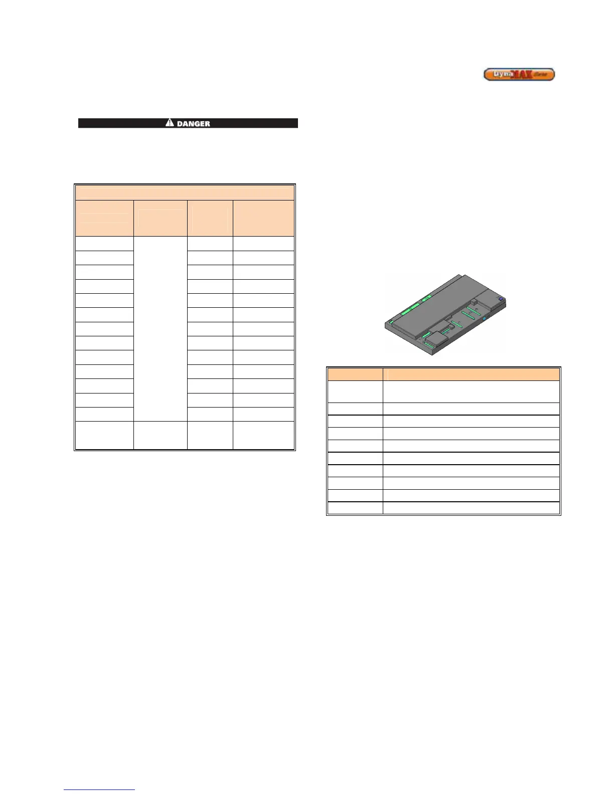
Figure 22: DynaMax Controller
Table 15: Connector Description
Connector
Connector Description
J2
Provides 120V to the DynaMax
Controller
J6
3-Way Diverter Valve
J7
On-Board Pump
J13
High-Limit, Gas Valve, Flame Sensor
J9
Fan Power, Fan Modulation
J5
Various Sensors
J16
Safety Switches
J12
Spark Return Signal
T2
Spark Igniter
F1
3.15A Fuse
5.3.1 SERVICE PARTS
The DynaMax Controller is not repairable. Any modification
or repairs will invalidate the warranty and may create
hazardous conditions that result in property damage,
personal injury, fire, explosion and/or toxic gases. A faulty
direct spark igniter MUST be replaced with a new factory
part. DO NOT use general purpose field replacement parts.
Each appliance has one DynaMax Controller, one direct
spark igniter and one flame sensor. A list of recommended
spare parts is available.
5.3.2 IGNITION MODULE LOCKOUT FUNCTIONS
The DynaMax Controller may lockout in either a manual
reset condition requiring pushing the reset button to recycle
the control for a CSD1 requirement or an automatic reset
condition. Pushing the reset button on the control panel is
the only way to reset the DynaMax Controller that is in a
hard lockout condition. The reset button is active after the
post purge cycle when there is a lockout condition as
indicated by the LCD display. Turning the main power “OFF”