PART 6 CONTROL PANEL
6.1 DYNAMAX CONTROLLER
The appliance is provided with an operator interface panel at
the front. On a DynaMax Wall Hung boiler the DynaMax
Controller can be accessed by removing the upper stainless
steel jacket and the lower black sheetmetal jacket which are
each held on by two (2) screws. On a DynaMax Floor Mount
boiler the DynaMax Controller can be accessed by carefully
lifting off the black-coloured Top cover which is held on by
four (4) snap lock fasteners.
The Boiler Temperature Controller (BTC) for this appliance is
a proprietary Camus DynaMax Controller. It initiates the local
call for heat and sets the target supply (appliance outlet)
water temperature. This controller accommodates heating
and domestic water control with multiple modes of operation
which provide set point as well as reset control. It provides
the following:
• Readings of inlet and outlet water temperatures, stack
temperatures, domestic hot water temperature, flame
current, status of heater operation, etc.
• Operation as an auto reset limit.
• Operation as a control for discharge water temperature.
• Optional tank mounted sensor used in conjunction with
outlet sensor for domestic hot water.
• Adjustable target temperature
• Display of run hours for maintenance purposes. Counter
displays run time up to 10,000 hours. Pressing the
RESET button will reset the counter.
• Molex, Stocko and AMP connectors for ease of service.
• Error message display.
6.2 SETTING THE DYNAMAX CONTROLLER
Press the MENU button and then select the desired setting
using the PREVIOUS and NEXT Buttons. When the desired
setting is satisfied press the ENTER key and this will save
the last setting. In normal operating mode the inlet
temperature, outlet temperature, and ON hours can be
viewed by pressing the PREVIOUS and NEXT key. After
checking the settings allow the control to return to normal
operation on its own.
6.3 CENTRAL HEATING MODES
Mode 0: Central Heating without Outdoor Reset
In this mode no outdoor sensor is needed. If the room
thermostat closes, the pump is switched on.
Burner On:
Supply Temp < CH Setpoint – CH Hysterese
Burner Modulation:
CH Setpoint
Burner Off:
Supply Temp > CH Setpoint + CH Hysterese
If the room thermostat opens the burner is switched off and
the pump runs on for post pump (default: 30 sec).
The anti-freeze monitor on each boiler will monitor the inlet
water temperature and when it drops below 50
o
F (10
o
C) it
will bring on the pump to prevent freezing of the heat
exchanger.
Mode 1: Central Heating with Outdoor Reset and Thermostat
Control
This mode will only function when an outdoor sensor is
connected. The set point is calculated depending on the
outdoor temperature and the burner will react on the room
thermostat. The central heating set point is calculated as
follows:
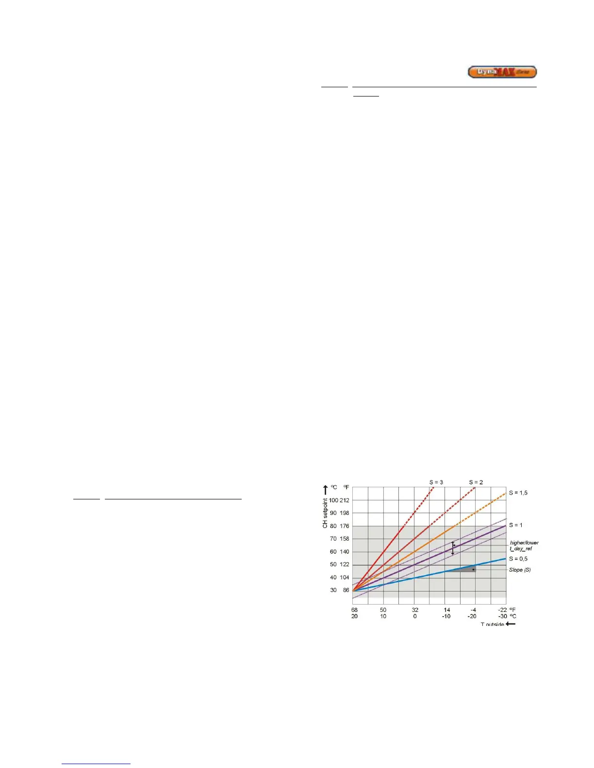
ch_setpoint = t_day_ref + [(68 – T_outdoor) * Slope]
To assist with programming a suitable outdoor reset curve it
would be advised to consult a qualified service technician
using DynaMax Outdoor Reset Calculator.xls
t_day_ref is the reference temperature for central heating set
point when T_outdoor is 68
o
F (20
o
C). T_day_ref is a user
settable parameter.
The Slope can be set via the menu between 0.1 to 5.0 with
steps of 0.1.
The calculated central heating set point is limited between
41
o
F (5
o
C) and 194
o
F (90
o
C).
The outdoor temperature used for the central heating set
point calculation is measured once a minute and averaged
with the previous measurement. This is done to avoid drastic
changes to the boiler when outdoor temperature fluctuates
rapidly.
Burner On:
Supply Temp < CH Setpoint – CH Hysterese
Burner Modulation:
CH Setpoint
Burner Off:
Supply Temp > CH Setpoint + CH Hysterese
The anti-freeze monitor on each boiler will monitor the inlet
water temperature and when it drops below 50
o
F (10
o
C) it
will bring on the pump to prevent freezing of the heat
exchanger.
Figure 22: Outdoor Reset Curve