It is important that all gas appliances be serviced by a
qualified technician trained by Camus Hydronics. It is in your
own interest and that of safety to ensure that all local codes,
and all the “NOTES” and “WARNINGS” in this manual are
complied with. To service or adjust this appliance, it is
imperative that the serviceman utilize a combustion analyzer
to read CO
2
and CO according to Camus Hydronics
recommendations.
Listed below are items that must be checked to ensure safe
reliable operations. Verify proper operation after servicing.
11.1 EXAMINE THE VENTING SYSTEM
Examine the venting system at least once a year. Check
more often in the first year to determine inspection interval.
Check all joints and pipe connections for tightness, corrosion
or deterioration. Flush the condensate drain hose with water
to clean. Clean screens in the venting air inlet system as
required. Have the entire system, including the venting
system, periodically inspected by a qualified service agency.
11.2 VISUALLY CHECK MAIN BURNER FLAMES
At each start up after long shutdown periods or at least every
six months. A burner view port is located on the combustion
chamber front door.
The area around the burner view port is hot and direct
contact could result in burns
Figure 59: Normal Burner Flame Profile (short dense
and blue)
• Normal Flame: A normal flame at 100% of burner input
is blue, with a well defined flame and no flame lifting.
• Yellow Tip: Yellow tipping can be caused by blockage
or partial obstruction of air flow to the burner.
• Yellow Flames: Yellow flames can be caused by
blockage of primary air flow to the burner or excessive
gas input. This condition MUST be corrected
immediately.
If improper flame is observed, examine the venting system;
ensure proper gas supply and adequate supply of
combustion and ventilation air.
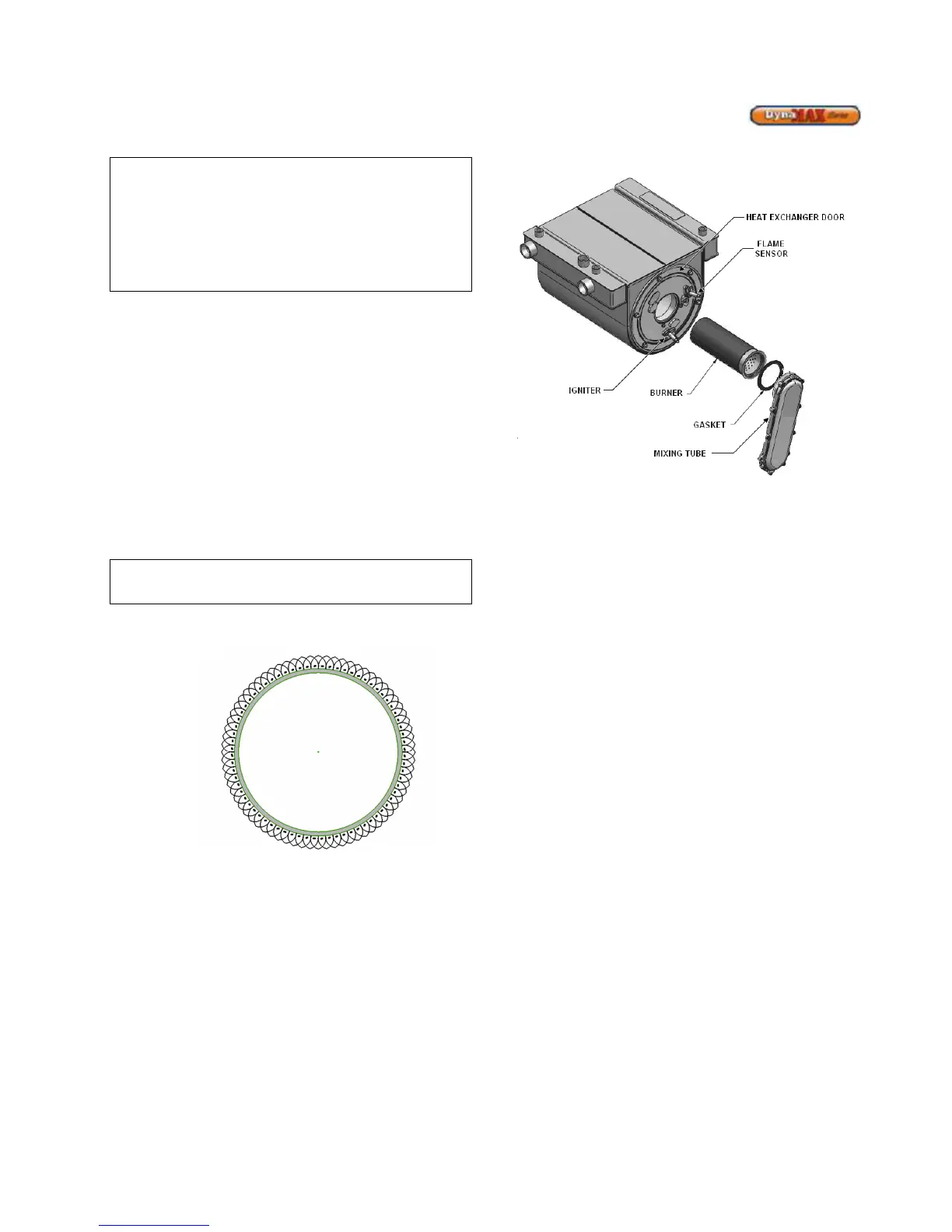
11.3 CLEANING BOILER HEAT EXCHANGER
Figure 60: Heat Exchanger & Burner Assembly
1) Shut down boiler:
a) Turn the main power off to the boiler
b) Shut off gas supply at the main manual valve in
the gas piping of the main appliance
c) DO NOT drain the boiler unless it will be exposed
to freezing temperatures. If using antifreeze
prevention fluid in the heat exchanger, DO NOT
drain.
2) Allow time for the boiler to cool to room temperature if it
has been firing.
3) Wall Hung: Remove both the stainless steel upper
jacket and the lower sheetmetal jacket.
Floor Mount: Remove front stainless steel panel.
4) Remove igniter and flame sensor electrodes. If
necessary, clean with steel wool. DO NOT use
sandpaper.
5) Remove the fan/ mixing tube assembly from the heat
exchanger door.
6) Remove burner.
7) Examine burner and clean if required as per 11.7.1.
8) Examine heat exchanger surfaces to determine if
cleaning is required. If cleaning is required remove the
(6) nuts fastening the heat exchanger flange from the
heat exchanger.
9) Use a vacuum cleaner to remove any debris that has
collected on the heat exchanger surfaces. DO NOT use
any type of solvent.
10) Finish cleaning by wiping down the boiler heating
surfaces with a clean, damp cloth.
11) Re-install the heat exchanger door by evenly torquing
down the (6) nuts to 3 ft-lbs, burner, igniter and flame
sensor, and fan/ mixing tube assembly. Fasten the nuts
back to the heat exchanger assembly.
12) Re-connect the fan assembly to the boiler mixing tube.