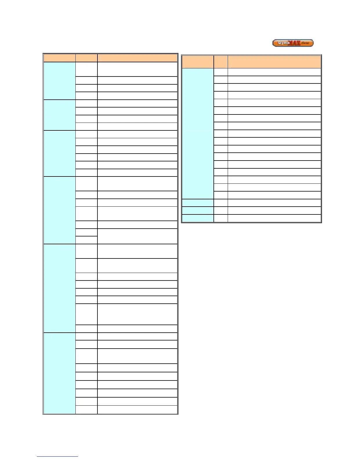
EasyManua.ls Logo

Camus Hydronics DynaMax DMH081 - Detailed Connector Description

Camus Hydronics DynaMax DMH081
93 pages
Print Icon
To Next Page IconTo Next Page
To Previous Page IconTo Previous Page
Loading...
86
15.5
DETAILED CONNECTOR DESCRIPTION
Connector
Pin #
Connector Description
J2
Provides 120VAC to the
DynaMax Controller
1
Earth/ Ground
2
120VAC Neutral
3
120VAC Live
J6
3-Way Diverter Valve
1
DHW 120VAC Live
2
CH 120VAC Live
3
120VAC Neutral
J7
On-Board Pump
1
Not Used
2
Pump 120VAC Neutral
3
Not Used
4
Not Used
5
Pump 120VAC Live
J13
High-Limit, Gas Valve, Flame
Sensor
1
120VAC Ground
2
Flame Sensor
3 Gas Valve 120VAC Neutral
4
Gas Valve 120VAC Live
5
High-Limit Safety
6
J9
Fan Power, Fan Modulation
1 Fan 120VAC Earth/ Ground
2
Fan 120VAC Live
3
Fan 120VAC Neutral
4
Fan Signal +
5
Fan Hall Effect Signal
6
Fan Pulse Width Modulation
(PWM) Signal
7
Fan Signal -
J16
Various Sensors
1
Flow Switch
2 Air Switch
3
Flow Switch
4
Air Switch
5
Not Used
6
Not Used
7
Not Used
8
Not Used
Connector
Pin
# Connector Description
J5
Various Sensors
1
Room Thermostat, 24VAC
2
Control Panel, +
3
Supply/Outlet Sensor
4
Return/Inlet Sensor
5
DHW Sensor/ Tank Stat
6
Flue/Stack Sensor
7
System Sensor
8
Outdoor Sensor
9
Room Thermostat, 24VAC
10
Control Panel, -
11
Supply/Outlet Sensor
12
Return/Inlet Sensor
13
DHW Sensor/ Tank Stat
14
Flue/Stack Sensor
15
System Sensor
16
Outdoor Sensor
J12
Spark Return Signal
T2
Spark Igniter
F1
3.15A Fuse

Table of Contents

Related product manuals