4.8 FLOW PROVING DEVICE (wall mount
models and combination models only)
Figure 19: Flow Proving Device
The flow proving device is designed to detect when flow is
present. This is done by detecting the amount of current
(amperes) that exists in the neutral wire from the pump.
When the current becomes too low a flow switch error is
displayed indicating a lack of water inside the boiler. The
flow proving device is provided on all DynaMax wall mount
models (DM 80 – 250) and combination floor model units
(213 – 803). This switch is factory wired.
Table 13: Flow Proving Device Indicator LED’s
Wall Mount
LED Illuminated Symptom
Front Normal operation
Rear Current under trip point
Floor Mount
LED Illuminated Symptom
Left Normal operation
Right Current under trip point
When testing the operation of the flow proving device always
ensure that 115Vac is being supplied to the pump.
4.9 WATER FLOW SWITCH (Floor mount
hydronic and DHW models only)
A water flow switch is shipped loose and is to be installed in
the outlet piping on all floor model heating boilers (DM 211-
801) and hot water supply heaters (DM 212 – 802). The flow
switch is to be installed in a horizontal run of pipe in order to
provide effective contact. The flow switch is to be wired into
the DynaMax terminal board labelled ‘Flow/LWCO’.
4.10 LOW WATER CUTOFF (If Equipped)
If this boiler is installed above radiation level, a low water
cut-off device must be installed at the time of boiler
installation. Some local codes require the installation of a low
water cut-off on all systems. Electronic low water cut-offs are
available as a factory supplied option on all models. Low
water cut-offs should be tested every six months. The
normally open switch contact of the low water cutoff is to be
wired in series with the flow switch. This can be wired into
the DynaMax terminal labelled ‘Flow/LWCO’.
CAUTION
Remove jumper when connecting to 24 VAC circuit.
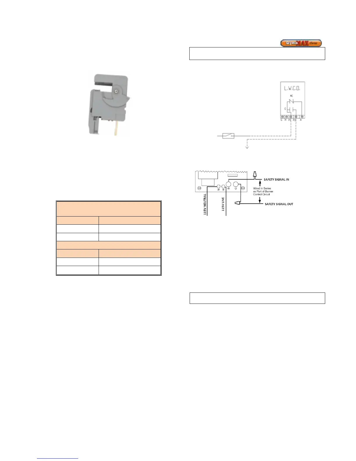
Figure 20: Low Water Cut Off Electrical
Connections (Watts)
Figure 21: Low Water Cut Off Electrical Connections (ITT)
4.11 RELIEF VALVE
This appliance is supplied with a relief valve sized in
accordance with ASME Boiler and Pressure Vessel Code,
Section IV (“Heating Boilers”). This component is shipped
loose. No valve is to be placed between the relief valve, and
the appliance. To prevent water damage, the discharge from
the relief valve shall be piped to a suitable floor drain for
disposal when relief occurs. No reducing couplings or other
restrictions shall be installed in the discharge line. The
discharge line shall allow complete drainage of the valve and
line. Relief valves should be manually operated at least once
a year.
Avoid contact with hot discharge water
4.12 DHW TUNING VALVE (combination models
only)
A DHW tuning valve is provided with all DynaMax
combination models. In cases where flow control is not
possible by the end user the DHW tuning valve is designed
to act as a maximum flow controller. The tuning valve is
designed to provide the correct amount of hot water for each
particular DynaMax model and application. Refer to section
12.9 Domestic Hot Water with Plate Heat Exchanger for
further details.