9.3 SYSTEM MONITOR DISPLAY
From MENU display;
1) Use [NEXT] to select ‘System Monitor’
2) Press [ENTER]
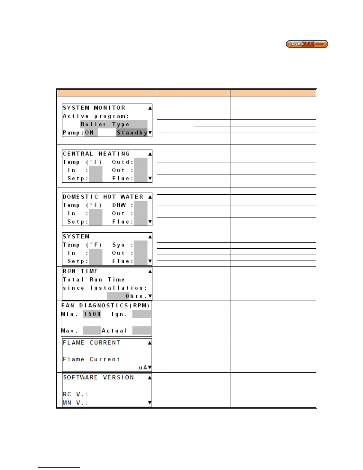
Display Display Readout Description
Active
Program
MASTER
Boiler is designated as a Master
boiler in the cascade setup
SLAVE
Boiler is designated as a Slave boiler
PUMP
ON
Pump is active
OFF
Pump is inactive (idle)
STATUS Standby
Heating and DHW Request (if
equipped) is satisfied
Outd
Outdoor Temperature (if equipped)
In
Boiler Return/Inlet Water
Temperature
Out
Boiler Supply/ Outlet Water
Temperature
CH Setpoint Temperature
Flue
Boiler Flue Temperature
DHW
DHW Temperature (if equipped)
In
Boiler Return/Inlet Water
Temperature
Out
Boiler Supply/ Outlet Water
Setp
DHW Setpoint Temperature
Flue
Boiler Flue Temperature
Sys
System Temperature of Primary
Loop
In Return/Inlet Temperature to Boiler
Supply/Outlet Temperature to Boiler
Setp Central Heating Setpoint
Total Run Time Since
Installation
Monitors the amount of operational
time since the DynaMax was
installed. The timer starts counting
as soon as it receives a flame signal
to the time the flame signal
disappears
Min. Programmed Minimum Fan Speed
Max. Programmed Maximum Fan Speed
Ign. Programmed Ignition Fan Speed
Actual
Actual Fan Speed updated in real-
time
Flame Current
7-9µA: High Fire
3-5 µA: Low Fire
Software Version
MN: 848MN-7R software version
RC: 848-RC software version