12.14 Write Functionality
The DynaMax Ignition module may be only reset when it is in
error. Only manual reset errors can be reset by writing
0x4000 to the Reset & R/W control holding register (0x001A)
of the Modbus interface (this sets the MN reset bit of the
Reset & R/W control holding register) The 848IF then sends
a reset command to the DynaMax Ignition Module over the
established link.
The Reset & R/W control register of the MN (0x001A) also
controls the reading and writing of the DynaMax Ignition
Module holding registers. Each bit of the Reset & R/W
control register corresponds with one parameter of the
Read/Write holding registers table. When a bit in the Reset &
R/W control is clear the data in the corresponding holding
register byte is fetched from the DynaMax Ignition Module
into the 848IF. When a bit in the Reset & R/W control
register is set the data in the corresponding holding register
byte is sent from the IF to the MN. To set an RC parameter
through Modbus first set its bit in the Reset & R/W control
register. This stops the parameter being fetched from the
MN. Then write the desired value into the parameters
holding register. The following table lists the Reset & R/W
control bits and corresponding parameters.
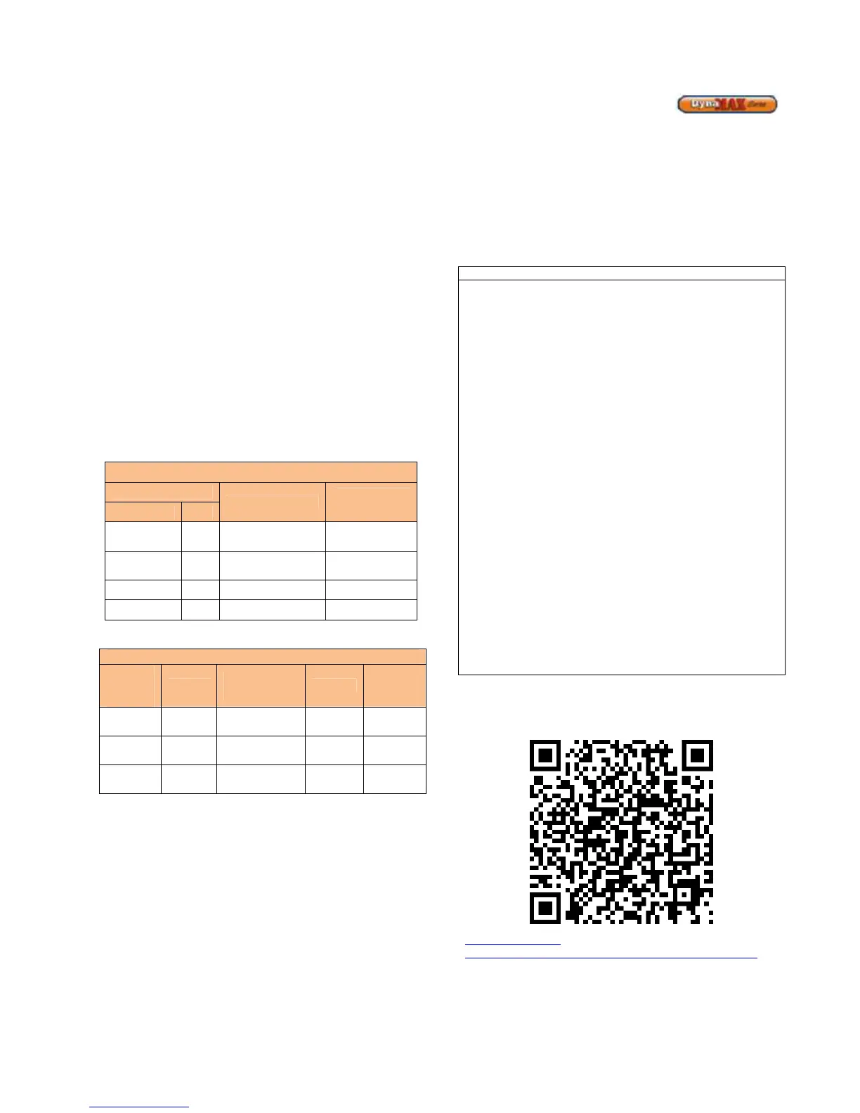
Table 40: Modbus Read/Write Registers
Read/Write Holding Registers
Item Index
Parameter Name
Holding
Registers
Word Byte
Control 0x001A
14 High Byte 14 CH_Setpoint 0x001E
14 Low Byte 15 DHW_Setpoint 0x001E
Table 41: Modbus Control Bits
R/W
control
register
bit
MN_Parameter
Name
Byte
Holding
Register
Low byte
1 CH_Setpoint 14
High byte
14 MN Reset bit
12.14.1 Write CH Setpoint
1) Issue a Modbus write single holding register
command writing 0x0002 to the Reset & R/W
control register located at 0x001A to switch from
CH set point reading to writing
2) Calculate the scaled set point = (((x-
32)/1.8)+10)*2*256
3) Issue a Modbus write single holding register
command writing the scaled calculated set point to
the 0x001E holding register
12.14.2 Write DHW Setpoint
1) Issue a Modbus write single holding register
command writing 0x001 to the Reset & R/W Control
register located at 0x001A to switch from DHW set
point reading to writing
2) Calculate the scaled set point = ((x-32)/1.8)+10)*2
3) Issue a Modbus write single holding register
command writing the scaled and calculated set
point to the 0x001E holding register
• Be advised that whenever the MN control is reset, it will
revert back to the setpoints stored in the E2Prom. After
every MN reset (automatic, through Modbus, via the IF
External Reset Input or via the RC reset button) the
Modbus controller must make sure that the error
condition has been resolved (ERROR_NUMBER =
0xFF) and then re-write the desired setpoints through
Modbus
• If the Reset & R/W control register bit of a setpoint is
set, the setpoint in the IF is communicated with the MN
as long as it differs from the setpoint in the DynaMax
Ignition Module. If the setpoint is then changed by
means of the Display or LabVision it will again be
different from the setpoint in the IF and thus, again be
overwritten by the setpoint in the IF. As long as the
Reset & R/W control register bit of the setpoint is set the
IF overrules all other setpoint settings. Clear the bit in
the Reset & R/W Control register to re-enable setting of
the setpoint by RC or LabVision
• When no Modbus communication (reading or writing) is
sensed for more than 4.25 seconds the R/W control
register bits will be reset. The R/W control register bits
will be reset. The R/W control register bits will also be
reset when undefined bits (ie. other than bits 0 and 1)
are set.
• In a cascade system only the setpoints of the MN board
connected directly to the IF board can be controlled.
For additional information for interfacing the boiler with
Modbus/Bacnet/LonWorks:
http://www.camus-
hydronics.com/Downloads/DynaMax_Protocol_Setup.pdf