PART 10 TROUBLESHOOTING
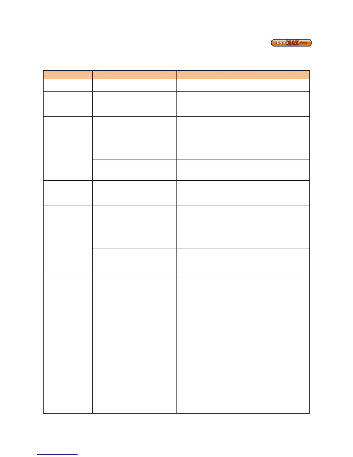
Table 29: Troubleshooting Table
COMPONENT FAILURE MODE ANALYSIS
Incoming Power
• Two wires interchanged • No effect on safety
• Live and Neutral wires are interchanged.
Transformer
Tripped
• The 24Volts and 120 Volts
wired are interchanged
• Transformer immediately burns out, replace
transformer
• Fuse on DynaMax Controller blows, replace 3.15A
fuse located at F1 on DynaMax Controller.
Pump Fails to
Circulate
• Wiring Issue • Check that wires are correctly wired from the
DynaMax Controller to the pump delay relay.
• Check that 115V is delivered to pump coil.
• Faulty Pump on a wet rotor
pump
• Pump impeller may be stuck. Use a flat head
screwdriver on face of pump to turn impeller
manually
• Replace Pump
• Air in the piping system
• Purge all air from the piping system
• Internal Fault on DynaMax
Controller
• Replace DynaMax Controller
Relief Valve
• System pressure exceeds relief
valve setting
• Replace the standard relief valve with a higher rated
valve up to the maximum pressure of the heat
exchanger.
• Improperly sized expansion tank.
Flow Proving
Device/ LWCO
• Flow Proving Device/ LWCO
contacts are open
• Verify LED’s on current sensing transformer during a
heat demand (wall hung)
• Check flow switch paddle (floor mount)
• Verify for closed valves or obstructions in boiler
piping
• Verify that all air has been purged from the system
• Verify that wiring is correct
• Blown Fuse • Replace 3.15A Fuse located at F1 on DynaMax
Controller.
• DO NOT use alternates as it may damage the
DynaMax Controller