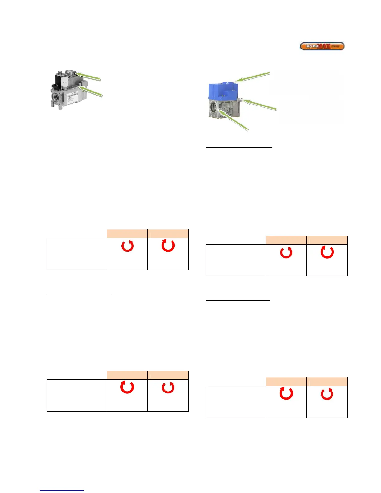
DM 299 – 399
Figure 57: DM 299 – 399 Gas Valve
To adjust the high-fire setting
Use the DynaMax Control Panel
Press the [MENU] button > select Appliance Settings and
press [ENTER] > select Boiler Control and press [ENTER] >
Enter the correct Installer passcode.
Select ‘Maximum power’ for high power. The DynaMax
should respond immediately and fire at maximum fan speed.
Locate the high-fire adjustment screw on the top side of the
gas valve. The screw can be identified by a red cylinder
casing around the screw. Turn the screw 1/8 turn in either
way for each adjustment to keep track of the adjustments.
After adjusting the screw wait a moment for the combustion
levels to stabilize before attempting to make any further
adjustments. Continue this procedure until combustion levels
are satisfied.
Increase CO2 Decrease CO2
High Fire
Adjustment
Counter-
Clock Wise
Clockwise
On the DynaMax Control Panel select ‘off’ to return to
normal operation.
To adjust the low fire setting
Use the DynaMax Control Panel
Press the [MENU] button > select Appliance Settings and
press [ENTER] > select Boiler Control and press [ENTER] >
Enter the correct Installer passcode.
Select ‘Minimum power’ for low power.
The DynaMax should respond immediately and fire at 1500
RPM. When this is achieved locate the low fire adjustment
screw as illustrated in Figure 57. When the correct
combustion values are achieved replace the screw cap back
on to the gas valve.
Clockwise
Counter-
Clock Wise
On the DynaMax Control Panel select ‘off’ to return to
normal operation.
DM 500 – 800
Figure 58: DM 500 - 800 Gas Valve
To adjust the high-fire setting
Use the DynaMax Control Panel
Press the [MENU] button > select Appliance Settings and
press [ENTER] > select Boiler Control and press [ENTER] >
Enter the correct Installer passcode.
Select ‘Maximum power’ for high power. The DynaMax
should respond immediately and fire at maximum fan speed.
Locate the input adjustment screw on the top side of the gas
valve. Turn the screw 1/8 turn in either way for each
adjustment to keep track of the adjustments. After adjusting
the screw wait a moment for the combustion levels to
stabilize before attempting to make any further adjustments.
Continue this procedure until combustion levels are satisfied.
Increase CO2 Decrease CO2
High Fire
Adjustment
Counter-
Clock Wise
Clockwise
On the DynaMax Control Panel select ‘off’ to return to
normal operation.
To adjust the low fire setting
Use the DynaMax Control Panel
Press the [MENU] button > select Appliance Settings and
press [ENTER] > select Boiler Control and press [ENTER] >
Enter the correct Installer passcode.
Select ‘Minimum power’ for low power.
The DynaMax should respond immediately and fire at 1500
RPM. When this is achieved locate the low fire adjustment
screw as illustrated in Figure 58. When the correct
combustion values are achieved replace the screw cap back
on to the gas valve.
Increase CO2 Decrease CO2
Low Fire
Adjustment
Clockwise
Counter-
Clock Wise
On the DynaMax Control Panel select ‘off’ to return to
normal operation.
fire air gas ratio adjustment
(use Torx 40 for adjustment,
clockwise increases CO
2
)
fire air gas ratio adjustment
(Use slotted screwdriver for
adjustment, counter-clockwise
increases CO
2
)
Low-fire air/gas ratio
adjustment, use slotted
screwdriver for adjustment,
clockwise increases CO
2
Lift top cover to access high fire
air/gas ratio adjustment (use 3mm
allen key for adjustment, counter-
clockwise increases CO
2)