Figure 62: Text Display Switch Setup
Wiring Setup
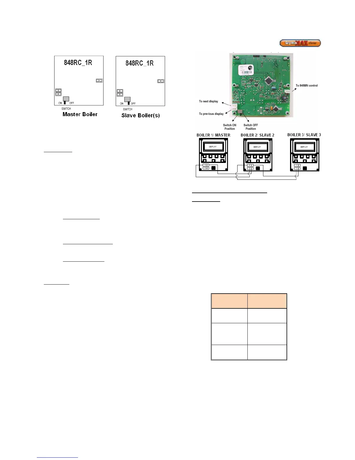
Refer to Figure 63 for a pictorial description of how to
connect the Cascade system together.
Master Boiler
The following needs to be done to the Master Text Display:
1) Connect the “To 848MN control” connector to the
DynaMax Ignition Control Board (848-MN). This
step was done by Camus unless the display was
disconnected in the field.
2) Place Switch to the “ON” position
3) Connect the “To next display” connector. This
connector serves as the communication point to the
next boiler. The “To previous display” connector is
to be left empty (no connection required)
Hydronic Heating
a. Wire system sensor into system sensor input
b. Attach call for heat/ enable signal to Room Stat
connection
DHW with Tank Sensor
a. Wire tank sensor into system sensor input
DHW with Aquastat
a. Wire aquastat into DHW sensor input
b. Wire system sensor into system sensor input
Slave Boiler
The following needs to be done to the Slave Text Display:
4) Connect the “To 848MN control” connector to the
DynaMax Ignition Control Board (848-MN). This
step is done by Camus unless the display was
disconnected in the field.
5) Place Switch to the “OFF” position
6) Connect the “To previous display” connector using
the connector from step 3.
If there are more than 2 boilers (up to 8) continue
with step 7.
If not, Wiring Setup is complete.
7) Connect the “To next display” connector. This
connector serves as the communication point to the
next boiler. When this is done all 3 connectors are
used on the back of the text display.
Figure 63: Text Display Detail
Programming the Cascade Setup
Master Boiler
Turn on the DynaMax Master Boiler and wait until the Date
and Time to appear.
1) Press [MENU]
2) Select “Appliance Settings” using the [NEXT]
button and press [ENTER].
3) Select “Cascade Control” using the [NEXT] button
and press [ENTER].
4) Enter the PIN Number to gain access. The numbers
can be moved up and down using the
[UP]/[DOWN] keys and press [ENTER] to move to
the next digit.
5) Select “Master Boiler 1” using the [UP]/[DOWN]
keys and press [ENTER] to confirm.
6) If a system sensor is used, select Enable System
Sensor
7) Select the proper Cascade Mode
System