External device
Network Interface
CPU
DRAM
FLASH
MEMORY
WIFI interface
FAX interface
NCU PCB
Wireless Lan PCB
Engine controller PCB
USB interface
Video interface
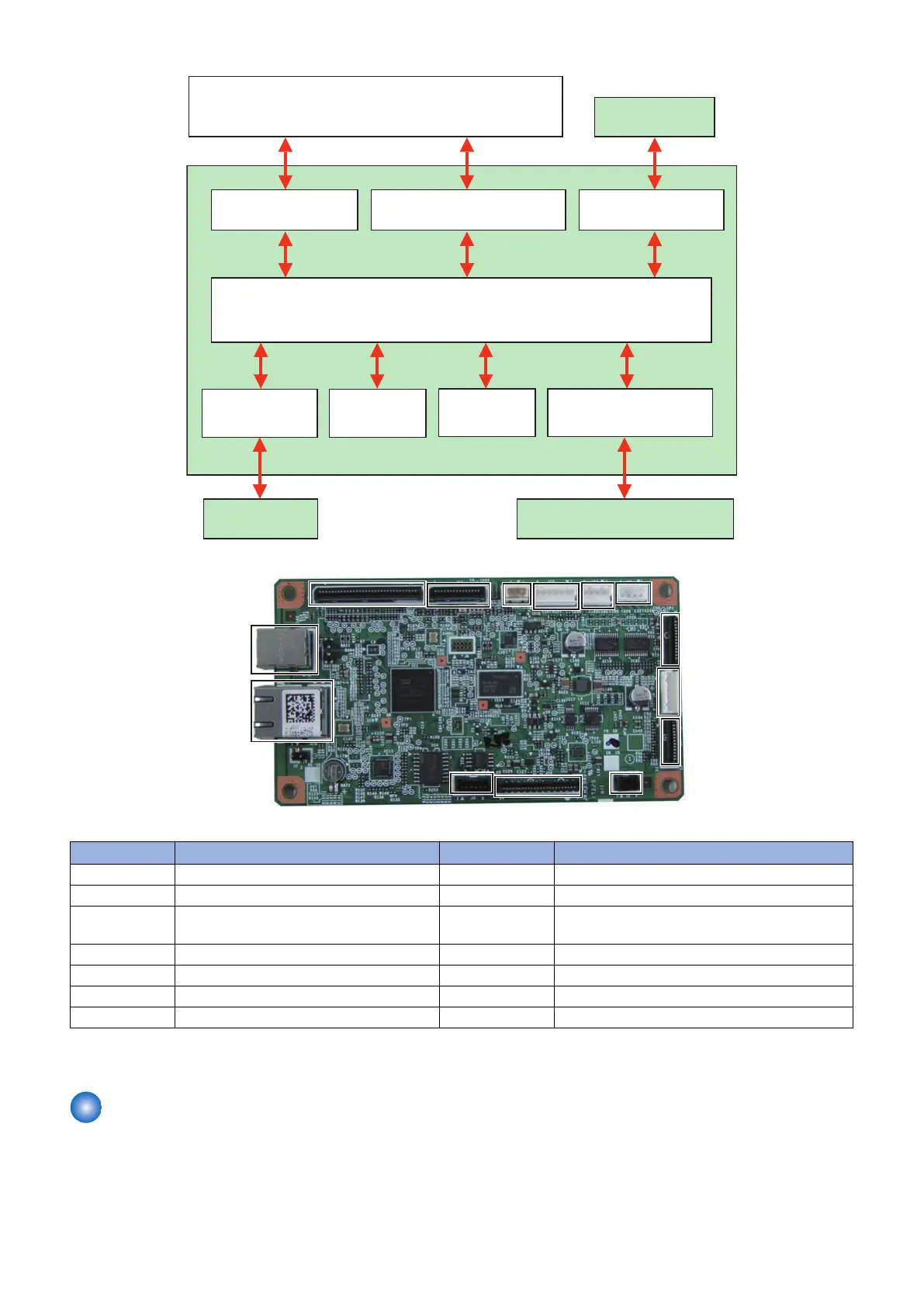
Main controller PCB
J9
J5
J4
J16J11J12J13J14
J18
J8
J1
J3
J7
J10
No. Destination / Role No. Destination / Role
J1 Multi-purpose Tray Sensor J10 * LAN Cable
J3 Not used J11 Reader Motor
J4 Engine Controller PCB J12 * ADF Document Sensor/ADF Document End Sen-
sor
J5 * Wireless Lan PCB J13 * ADF Solenoid
J7 USB J14 Contact Image Sensor
J8 Control Panel PCB J16 * ADF Motor
J9 Low Voltage Power Supply PCB J18 * NCU PCB
*: May not be installed according to the specification of applicable model.
Engine Controller PCB
The Engine Controller PCB is a circuit to control the operation sequences of this machine, and controlled by DC Controller and
High Voltage Power Supply in the Engine Controller PCB.
When the DC power is supplied through the low voltage power supply, the DC Controller starts to control the printer operation.
Then the DC Controller drives loads such as laser, motors, solenoids etc. according to the image data that is input by the main
controller when status becomes stand-by mode.
2. Technology
32