Power supply
Overview
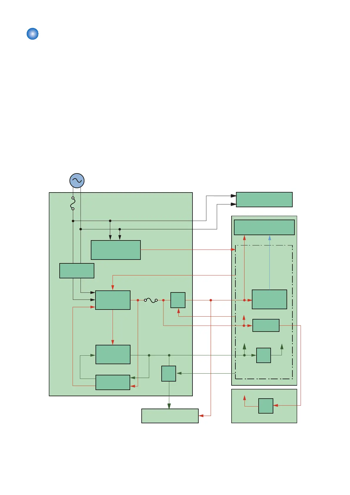
Low Voltage Power Supply PCB converts DC power supply from AC power supply to supply voltage to PCBs.
Description
The following shows a block diagram of the power supply.
• Low Voltage Power Supply PCB: Controls the temperature of the Fixing Heater of the Fixing Assembly and generates the
DC power supply required by the host machine.
• DC Controller: Distributes voltage provided by the Low Voltage Power Supply to respective load.
When the Low Voltage Power Supply PCB is connected to the inlet, AC power supply to the Low Voltage Power Supply PCB
starts.
AC power supply is used to drive the Fixing Heater. +24 V generation circuit in the power supply generates DC power voltage
+24V.
+3.3 V is generated from DC voltage +24 V, which is generated in the power supply, then supplied to the DC Controller and the
Main Controller.
DC Controller generates +5 V from DC voltage +24 V, and then supplies it to the High Voltage PCB.
Voltage generated by the Fixing Power Supply PCB and DC Controller is supplied to each load.
+24F
FET
FET
FET
FET
+3.3F
LVM
FREQSNS
Door SW
circuit
+3.3V +3.3U
+24U
+24V
+24V
24F ON
+24F +5R
+24P
3.3F ON
AC input
Low voltage power supply
Fuse
FU101
+24V
generation
circuit
+3.3V
generation
circuit
Protection
circuit
Motor PCB
DC controller
High voltage power supply
Fixing unit
+5V
generation
circuit
Main controller PCB
Rectifying
circuit
Engine controller PCB
Fuse
FU202
Frequency
detection circuit
(220-240V only)
2. Technology
36