Chapter 2
2-40
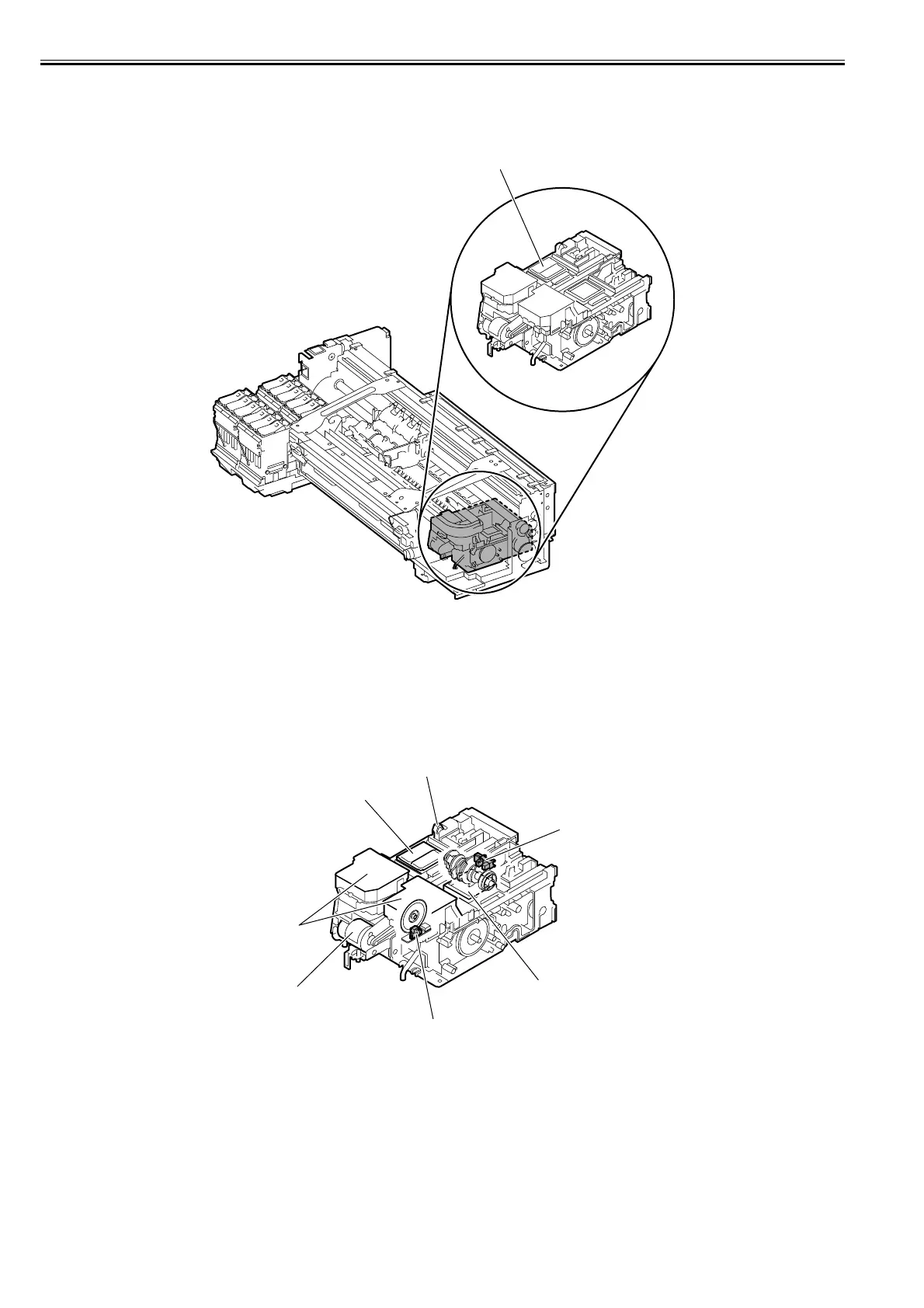
2.3.2.5.2 Structure of Purge Unit
0013-4382
iPF6100 / iPF6200 / iPF6000S / iPF6300 / iPF6350 / iPF6300S
F-2-28
a) Cap unit
The cap unit is used to cap the print head nozzles during capping and cleaning. The portion that touches the face plate is made from rubber. Two left caps are ar-
ranged for the printhead (six arrays of nozzles) installed in the carriage.
During cleaning, the caps used for both suction and capping are used to suck ink from the printhead using the suction pump.
Each of the right caps is used to cap the six arrays of nozzles.
This cap is used only for capping.
During capping, the caps are raised by the cap cams operated by the purge motor to cover the arrays when the carriage has moved to the home position, thus pro-
tecting the nozzles.
F-2-29
Purge unit
Carriage lockpin
Sub cap
Glycerin tank
Purge motor
Pump encoder encoder
Pump cam sensor
Cap