Chapter 4
4-67
4.3.21 PCBs
0020-2187
iPF6200 / iPF6000S
Do not replace the main controller PCB and maintenance cartridge relay PCB(ROM board) at the same time.
These PCBs store important data such as settings and carriage drive time. Before replacement of either PCB, the data stored in it is moved to the other PCB through
internal communication so that it can be taken over to the new PCB automatically. This is the reason why the two PCBs should not be replaced at the same time.
If you want to replace both PCBs at the same time, first carry out the procedure "Procedure for replacing the maintenance cartridge relay PCB(ROM board)" and
then carry out the procedure "Procedure for replacing the main controller PCB".
After replacing with the main controller PCB or maintenance cartridge relay PCB which are supplied as service parts, check that the firmware to the latest version.
a) Removing the main controller PCB
1) To remove the main controller PCB, open the top cover and remove the roll feed unit, left circle cover, tank cover, left cover, lower rear cover, lower rear left
cover and left rear cover.
Refer to DISASSEMBLY/REASSEMBLY > Points to note on Disassembly and Reassembly > External Covers.
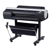
2) Remove the four screws[1] and remove the shield plate[2].
F-4-148
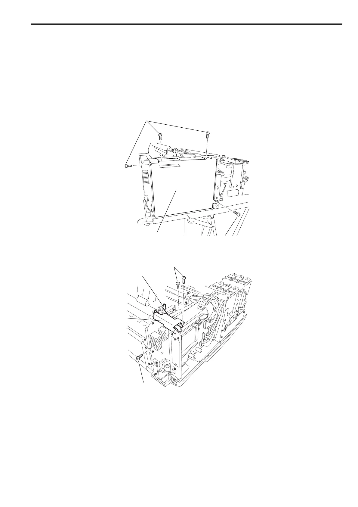
3) Remove the three screws[1], and then remove the shield cover[2] and the guide[3].
F-4-149
[2]
[1]
[1]
[1]
[3]
[2]
[1]