Step Action
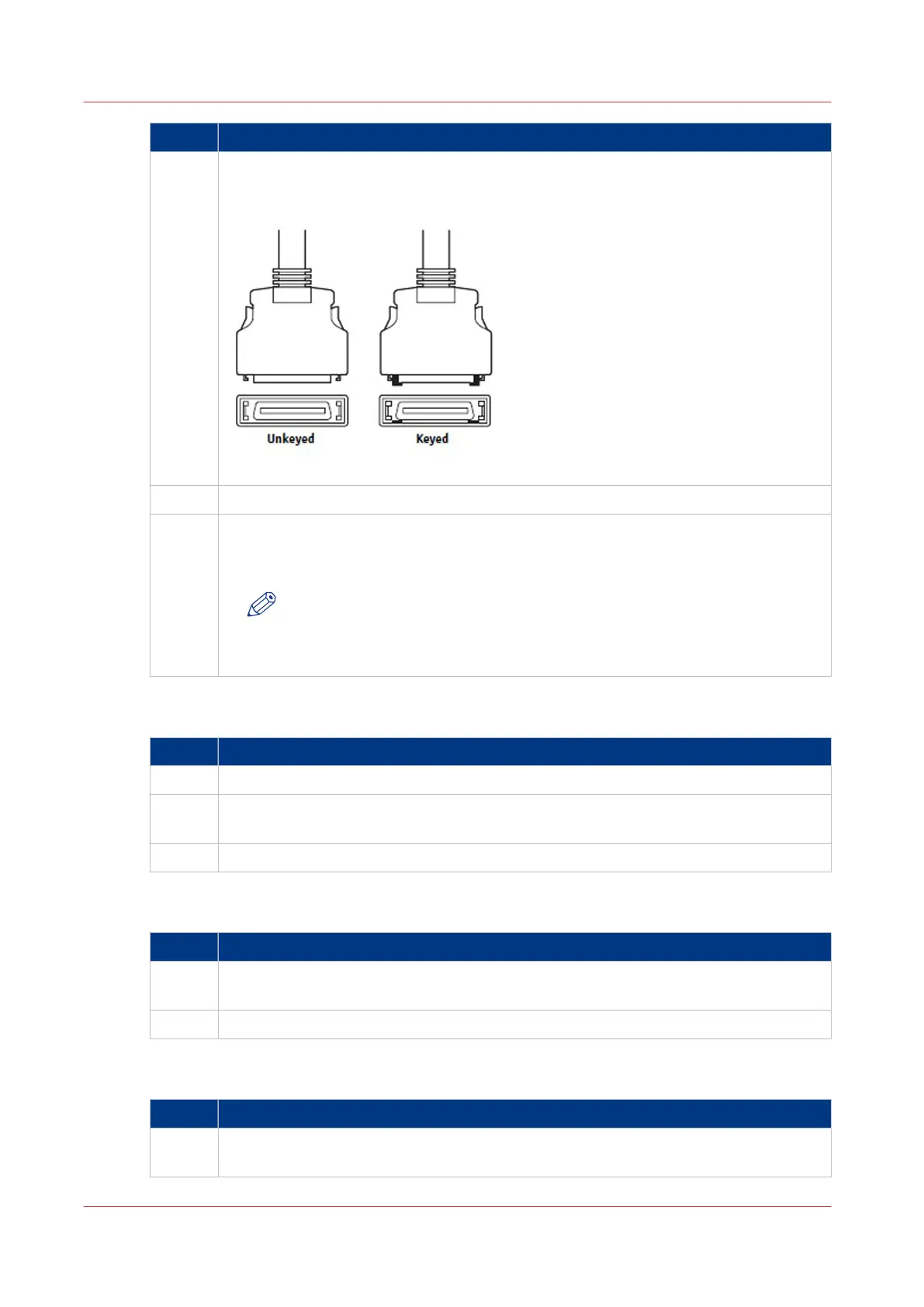
2 Locate the two copier interface cables, and identify the keyed and unkeyed connector
ends on each cable.
Each cable has one keyed connector and one un-keyed connector.
Fig.: Copier interface cable connections
3 Connect the cables to the interface ports on the copier.
4 Connect the other ends to their corresponding ports on the PRISMAsync.
.
Each cable connector is designed to fit only one way when properly oriented.
NOTE
If a cable connector does not fit into an interface port, change the orienta-
tion of the cable. Do not force a connection that is mis-keyed. Doing so may
permanently damage the port or the cable.
Connect the Operator Attention Light
Step Action
1 Install the Operator Attention Light to the backside of the copier
2 Connect the cable with the 9-pins D-sub connector to the connector on the backside of
the
PRISMAsync.
3 Connect the other side of the cable to the connector attached to the Attention Light
Connect to the network
Step Action
1
Connect one side of a straight-through Ethernet cable to the upper RJ45 connector on
the backside of the
PRISMAsync.
2 Connect the other side of the Ethernet cable to the Ethernet wall-outlet
Connect the power
Step Action
1 Connect recessed end of the power cable to the power connector on the back of the
PRISMAsync
.
4
Connect the PRISMAsync
20 Chapter 3 - Installation
PRISMAsync V3.2