EasyManuals Logo

Capstone Microturbine C1000 Series User Manual

Capstone Microturbine C1000 Series
122 pages
To Next Page IconTo Next Page
To Previous Page IconTo Previous Page
Page #30 background imageLoading...
Page #30 background image
Capstone Turbine Corporation • 16640 Stagg Street • Van Nuys • CA 91406 • USA
Installation Guide: Capstone C1000S/C800S/C600S with C1000 Series Controller
480064 Rev C (December 2018) Page 30 of 122
Capstone reserves the right to change or modify, without notice, the design, specifications, and/or contents of this document without
incurring any obligation either with respect to equipment previously sold or in the process of construction.
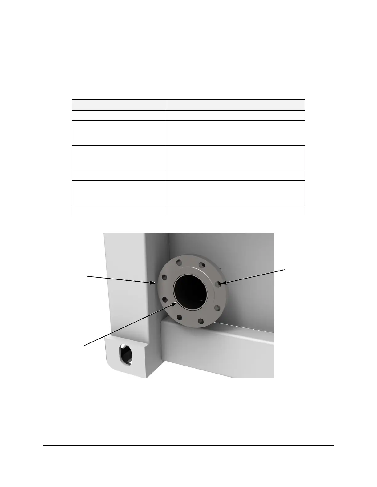
4.1. Fuel Connection
Refer to Table 2 and Table 3 for fuel connection specifications. The customer fuel connection is
shown in Figure 6 for gaseous fuels and Figure 7 for liquid fuels. Refer to C1000S, C800S, or
C600S O&I Drawing (Table 1) for further details.
Table 2. Gaseous Fuel Connection Specifications
Parameter
Specification
Pipe Diameter
102 mm (4 inch)
Flange:
Type
Diameter
ASME/ANSI B16.5 Class 150 (Raised Face)
229 mm (9 inch)
Bolt Holes:
Size
Bolt Circle
19 mm (3/4 inch) for 16 mm (5/8 inch) bolt
191 mm (7.5 inch)
Recommended Torque
136 Nm (100 ft-lb)
Pressure:
Natural Gas, High Pressure
Natural Gas, Low Pressure
534 ±17.2 kPag (77.5 ±2.5 psig)
18.1 ±16.4 kPag (2.63 ±2.38 psig)
Fuel Pressure Fluctuation
1 psi/sec
Figure 6. Gaseous Fuel Connection
Pipe
Bolt Hole
(8 Places)
Flange

Table of Contents

Questions and Answers:

Question and Answer IconNeed help?

Do you have a question about the Capstone Microturbine C1000 Series and is the answer not in the manual?

Capstone Microturbine C1000 Series Specifications

General IconGeneral
BrandCapstone
ModelMicroturbine C1000 Series
CategoryController
LanguageEnglish