Capstone Turbine Corporation • 16640 Stagg Street • Van Nuys • CA 91406 • USA
Installation Guide: Capstone C1000S/C800S/C600S with C1000 Series Controller
480064 Rev C (December 2018) Page 34 of 122
Capstone reserves the right to change or modify, without notice, the design, specifications, and/or contents of this document without
incurring any obligation either with respect to equipment previously sold or in the process of construction.
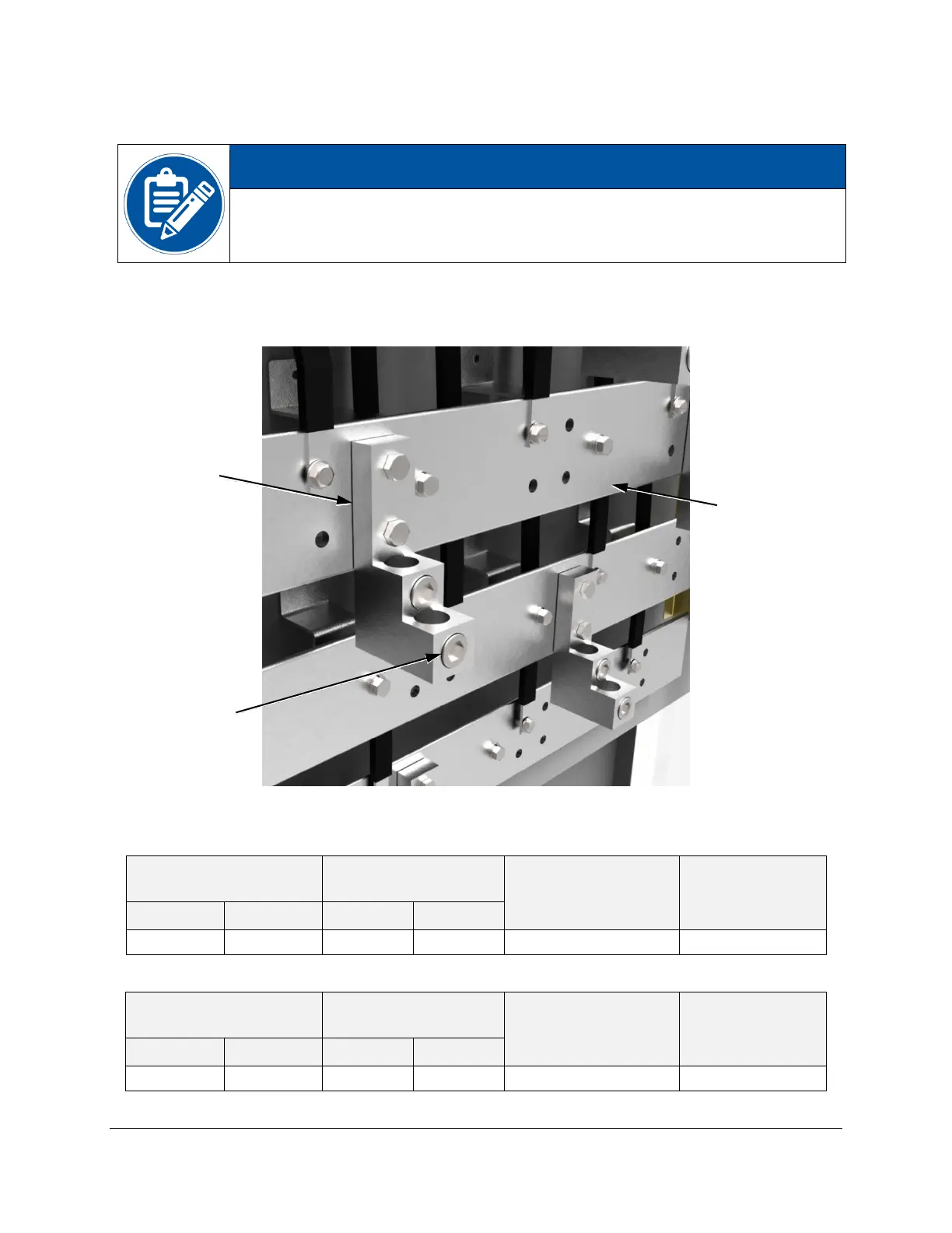
4.3.2. High Power Connections
Each phase bus bar provides four spaces on two lugs for power cable
connection per phase. If an installation requires more than four conductors
per phase, the installer can add additional lugs to each bus bar.
See Figure 5 for power cable connection locations on the C1000S/C800S/C600S microturbine.
Refer to Table 4 for N-L1-L2-L3 power cable specifications and Table 5 for PE chassis ground
cable specifications.
Figure 10. High Power Bus Bar Lugs
Table 4. N – L1 – L2 – L3 Lug Specifications
Table 5. Ground Bar Specifications

 Loading...