Capstone Turbine Corporation • 16640 Stagg Street • Van Nuys • CA 91406 • USA
Installation Guide: Capstone C1000S/C800S/C600S with C1000 Series Controller
480064 Rev C (December 2018) Page 37 of 122
Capstone reserves the right to change or modify, without notice, the design, specifications, and/or contents of this document without
incurring any obligation either with respect to equipment previously sold or in the process of construction.
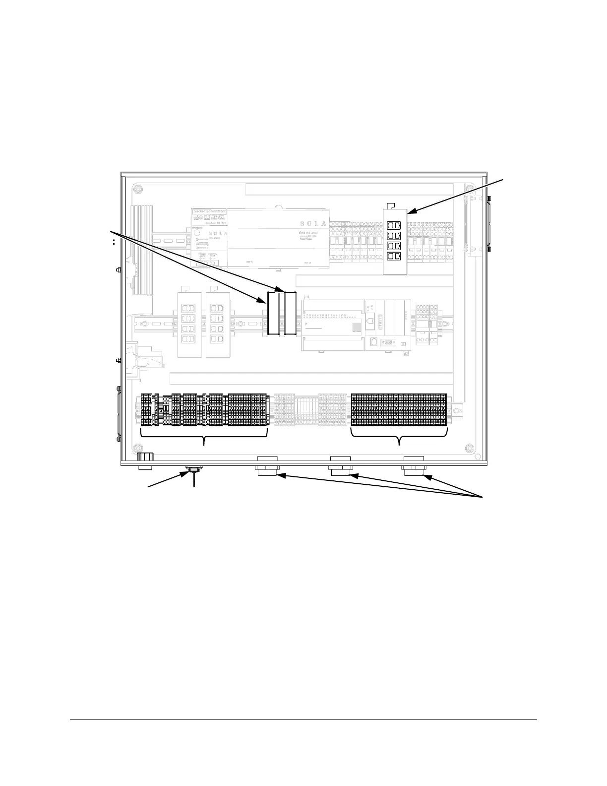
4.3.4. Controller Customer Connections
Make controller wire and Ethernet cable connections to the components shown in Figure 12.
Terminal block connections and specifications are shown in Figure 13 and Table 8. Refer to
Section 8 for wiring diagrams. Refer to the C1000S/C800S/C600S Technical Reference (Table 1)
for a detailed description of all controller wiring.
Figure 12. C1000 Series Controller Connections

 Loading...