Capstone Turbine Corporation • 16640 Stagg Street • Van Nuys • CA 91406 • USA
Installation Guide: Capstone C1000S/C800S/C600S with C1000 Series Controller
480064 Rev C (December 2018) Page 53 of 122
Capstone reserves the right to change or modify, without notice, the design, specifications, and/or contents of this document without
incurring any obligation either with respect to equipment previously sold or in the process of construction.
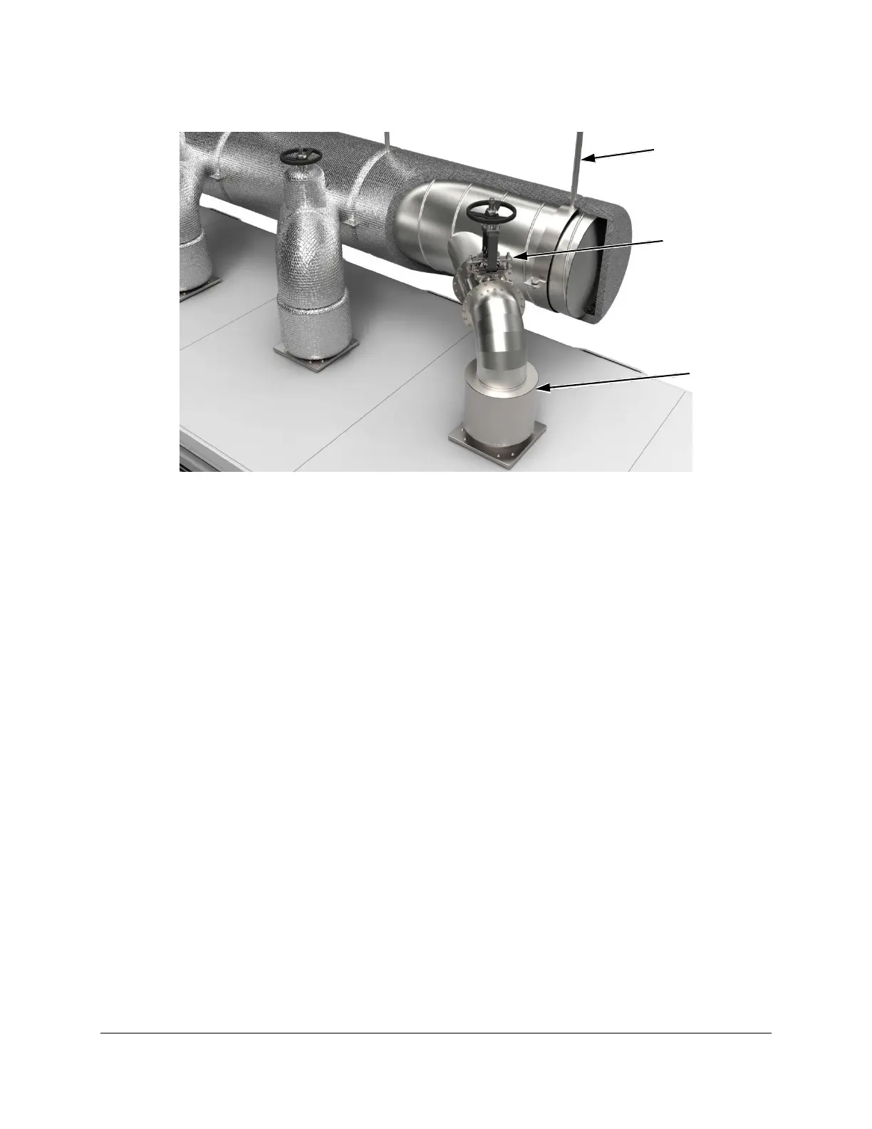
Figure 23. Ducting Installation Example
5.4.5.1. Capstone Backflow Valve Installation
When installing a backflow valve, ensure the following:
If installing the Capstone backflow valve in ducting that is not vertical (90°), the angle of
the damper must not be less than 25° above horizontal, as shown in Figure 24.
Make sure that the flapper hinge is installed at top dead center.
The flapper must form a good seal without binding.
Install a service port near the backflow valve for visual inspection.

 Loading...