Capstone Turbine Corporation • 16640 Stagg Street • Van Nuys • CA 91406 • USA
Installation Guide: Capstone C1000S/C800S/C600S with C1000 Series Controller
480064 Rev C (December 2018) Page 121 of 122
Capstone reserves the right to change or modify, without notice, the design, specifications, and/or contents of this document without
incurring any obligation either with respect to equipment previously sold or in the process of construction.
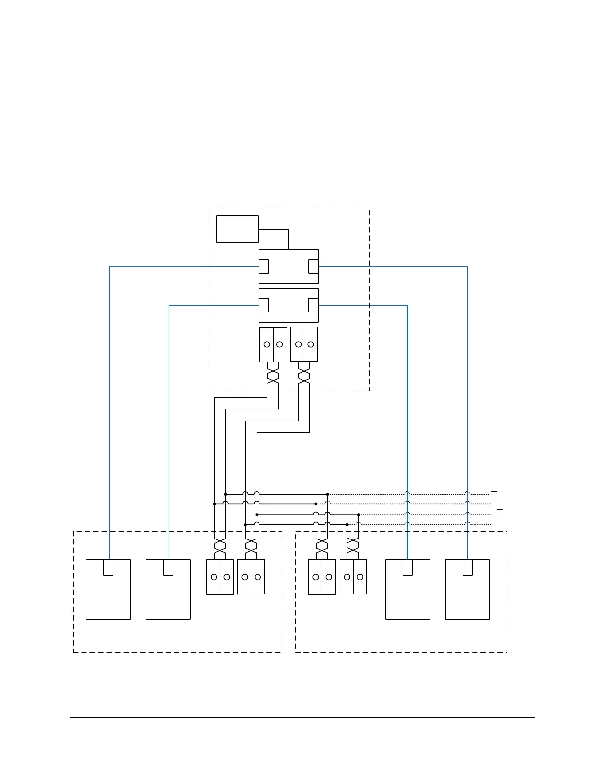
In addition to digital communications lines, hard-wired control connections also include:
A battery wake-up signal from the CLC to each C1000 controller at terminals TB1-54
and TB1-55.
A fault input from the CLC to each C1000 controller at terminals TB3-57 and TB3-58.
An optional global E-Stop signal from an E-Stop switch to the C1000 controller terminals
TB1-12 and TB1-13.
Figure 64 shows the digital communications and hard-wired connections from a Dual Mode CLC
to Dual Mode C1000’s.

 Loading...