Capstone Turbine Corporation • 16640 Stagg Street • Van Nuys • CA 91406 • USA
Installation Guide: Capstone C1000S/C800S/C600S with C1000 Series Controller
480064 Rev C (December 2018) Page 32 of 122
Capstone reserves the right to change or modify, without notice, the design, specifications, and/or contents of this document without
incurring any obligation either with respect to equipment previously sold or in the process of construction.
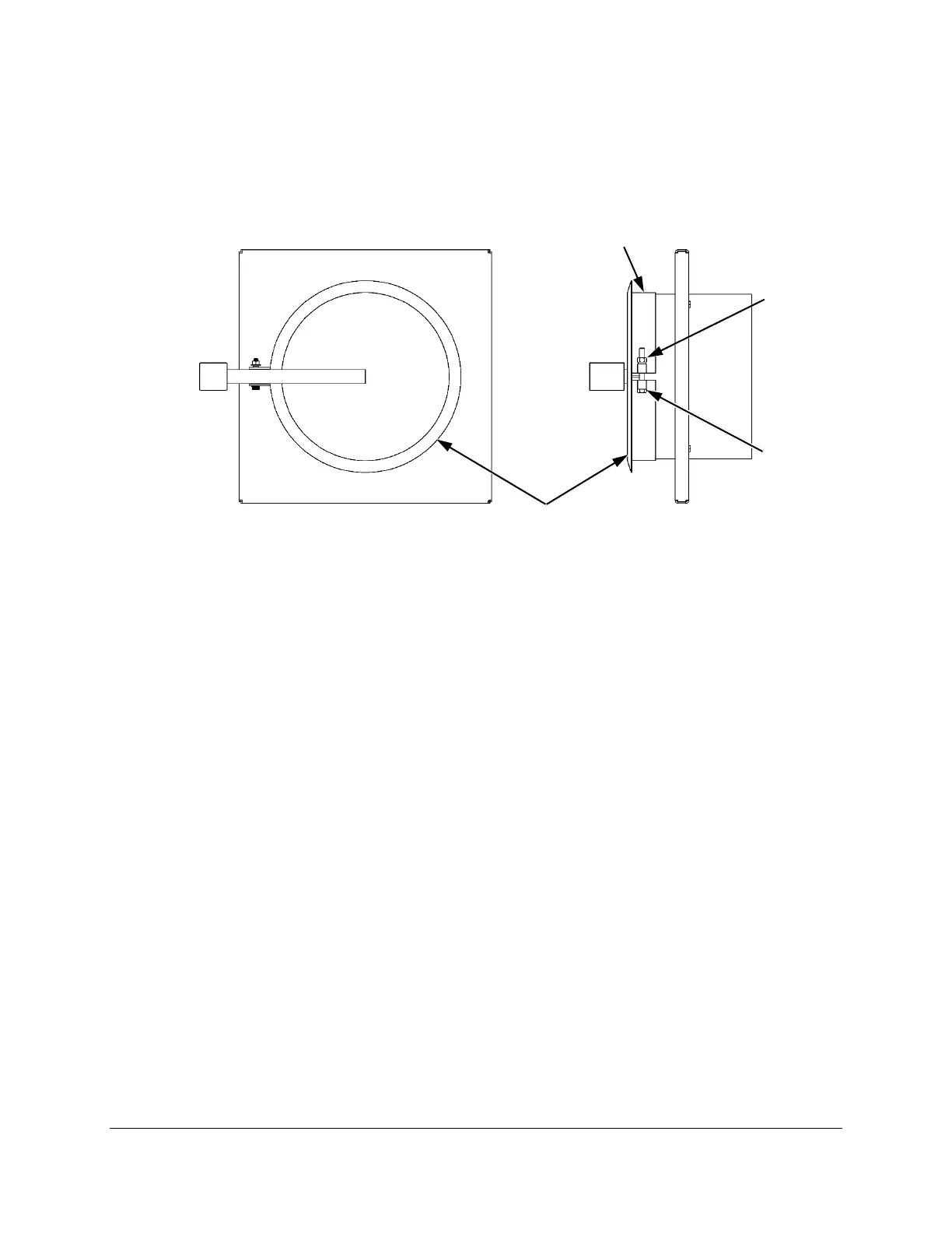
4.2.2. Rain Cap Removal
Remove the rain cap from the exhaust outlet assembly (Figure 8) by loosening the clamp ring,
which is secured by a hex screw and nut. The screw or nut can be adjusted using a 9/16-in.
wrench.
Figure 8. Exhaust Outlet Assembly
4.3. Electrical Connections
4.3.1. Electrical Conduit Installation
The access locations for all power and communication cables are shown in Figure 9. This includes
the floor access plates and side panel punch out locations. Punch holes in the side panel as
necessary only in the dimensions shown, and install water-tight conduit fittings in the punched
holes.
Before installing conduit fittings in an access plate, remove the access plate by removing the
bolts. Punch holes in each plate as necessary, and install water-tight conduit fittings in the
punched holes. The plates are secured by Class 8.8, M8 X 1.25 X 25 bolts at the factory. When
installing the access plate, torque each bolt to 25.5 Nm (18.8 ft-lb). If the factory-installed bolt
must be replaced, make sure the replacement fastener is corrosion resistant, zinc-plated steel
with M8 X 1.25 pitch thread size.
 Loading...