Capstone Turbine Corporation • 16640 Stagg Street • Van Nuys • CA 91406 • USA
Installation Guide: Capstone C1000S/C800S/C600S with C1000 Series Controller
480064 Rev C (December 2018) Page 46 of 122
Capstone reserves the right to change or modify, without notice, the design, specifications, and/or contents of this document without
incurring any obligation either with respect to equipment previously sold or in the process of construction.
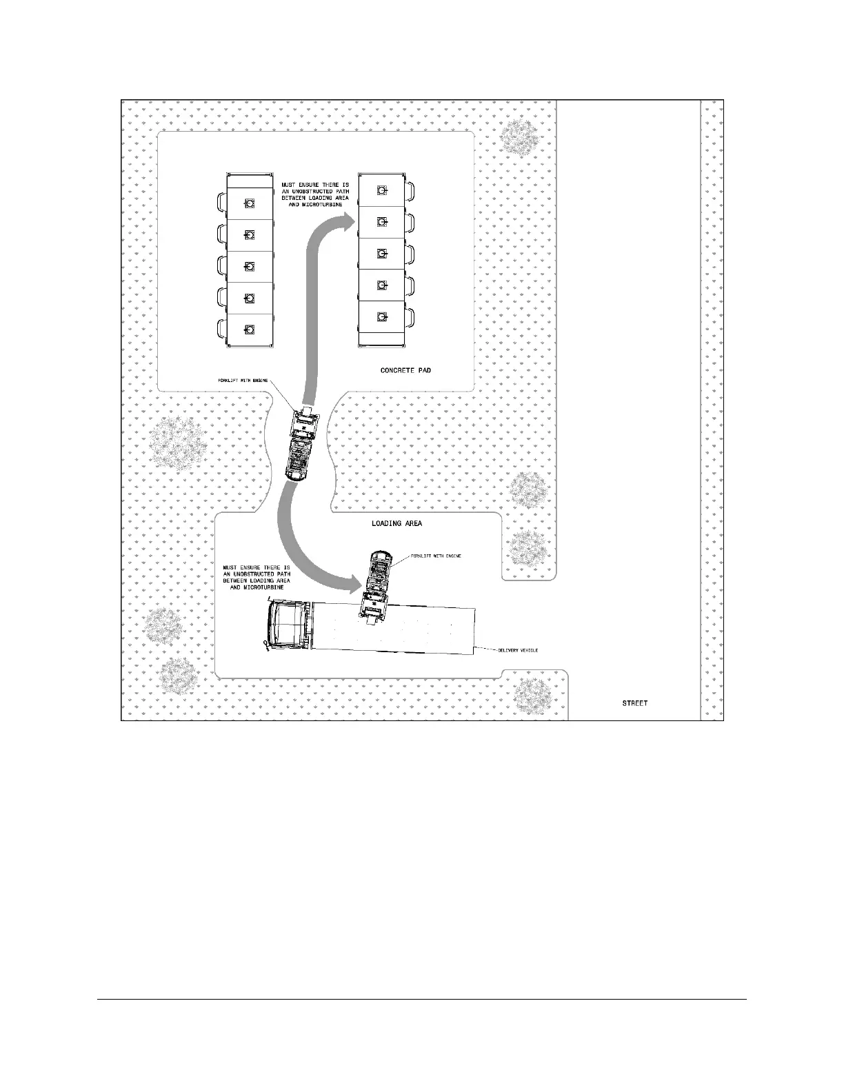
Figure 20. Example Site Path for Engine and Component Delivery
5.4. Ventilation
Proper ventilation of the air inlet and exhaust are critical to microturbine performance and
longevity. Microturbines require a large amount of air for both engine combustion and enclosure
cooling.
Airflow paths are shown in Figure 21. There are two separate air inlets in the
C1000S/C800S/C600S microturbine, one for engine combustion air, and one for cooling of
internal modules — electronics, fuel skids, etc. The Capstone microturbine exhaust also consists
of two components, the combustion air exhaust and the enclosure/electronics exhaust.
 Loading...