Capstone Turbine Corporation • 16640 Stagg Street • Van Nuys • CA 91406 • USA
Installation Guide: Capstone C1000S/C800S/C600S with C1000 Series Controller
480064 Rev C (December 2018) Page 76 of 122
Capstone reserves the right to change or modify, without notice, the design, specifications, and/or contents of this document without
incurring any obligation either with respect to equipment previously sold or in the process of construction.
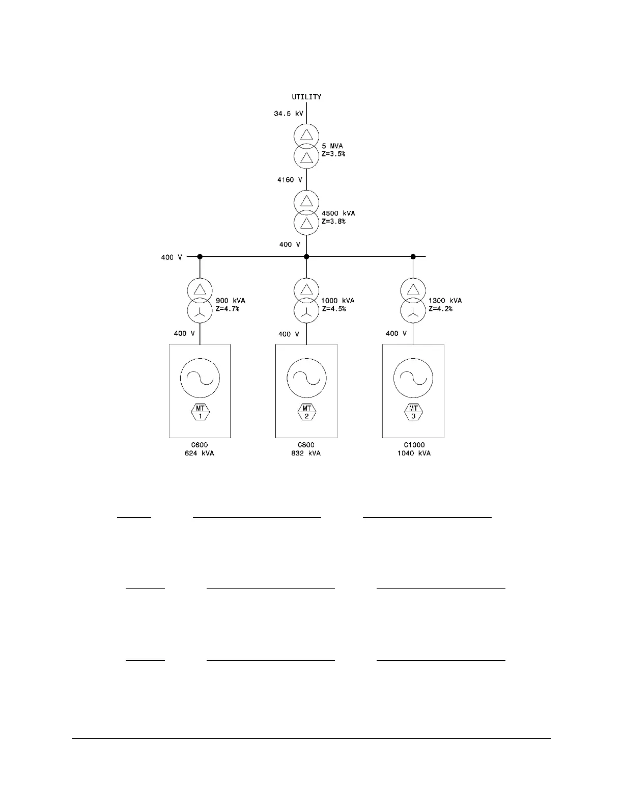
7.4.3.2. Example 2 – 400V Operation
Figure 30. Typical Transformer Installation with Impedance Percentages – 400 V
Microturbine #1 (C600S with 624 kVA):
𝑍 = 4.7%(
624 𝑘𝑉𝐴
900 𝑘𝑉𝐴
) + 3.8%(
624 𝑘𝑉𝐴 + 832 𝑘𝑉𝐴 + 1040 𝑘𝑉𝐴
4500 𝑘𝑉𝐴
) + 3.5%(
624 𝑘𝑉𝐴 + 832 𝑘𝑉𝐴 + 1040 𝑘𝑉𝐴
5000 𝑘𝑉𝐴
) + 0.5%
Z = 7.61%
Microturbine #2 (C800S with 843 kVA):
𝑍 = 4.5%(
843 𝑘𝑉𝐴
1000 𝑘𝑉𝐴
) + 3.8%(
624 𝑘𝑉𝐴 + 832 𝑘𝑉𝐴 + 1040 𝑘𝑉𝐴
4500 𝑘𝑉𝐴
) + 3.5%(
624 𝑘𝑉𝐴 + 832 𝑘𝑉𝐴 + 1040 𝑘𝑉𝐴
5000 𝑘𝑉𝐴
) + 0.5%
Z = 8.11%
Microturbine #3 (C1000S with 1040 kVA):
𝑍 = 4.2%(
1040 𝑘𝑉𝐴
1300 𝑘𝑉𝐴
) + 3.8%(
624 𝑘𝑉𝐴 + 832 𝑘𝑉𝐴 + 1040 𝑘𝑉𝐴
4500 𝑘𝑉𝐴
) + 3.5%(
624 𝑘𝑉𝐴 + 832 𝑘𝑉𝐴 + 1040 𝑘𝑉𝐴
5000 𝑘𝑉𝐴
) + 0.5%
Z = 7.04%
Since the calculated inductive impedances are less than the 10% maximum listed in the
C1000S/C800S/C600S Technical Reference (Table 1), the system design is acceptable.

 Loading...