Capstone Turbine Corporation • 16640 Stagg Street • Van Nuys • CA 91406 • USA
Installation Guide: Capstone C1000S/C800S/C600S with C1000 Series Controller
480064 Rev C (December 2018) Page 108 of 122
Capstone reserves the right to change or modify, without notice, the design, specifications, and/or contents of this document without
incurring any obligation either with respect to equipment previously sold or in the process of construction.
8. Communication
8.1. Ethernet Communication
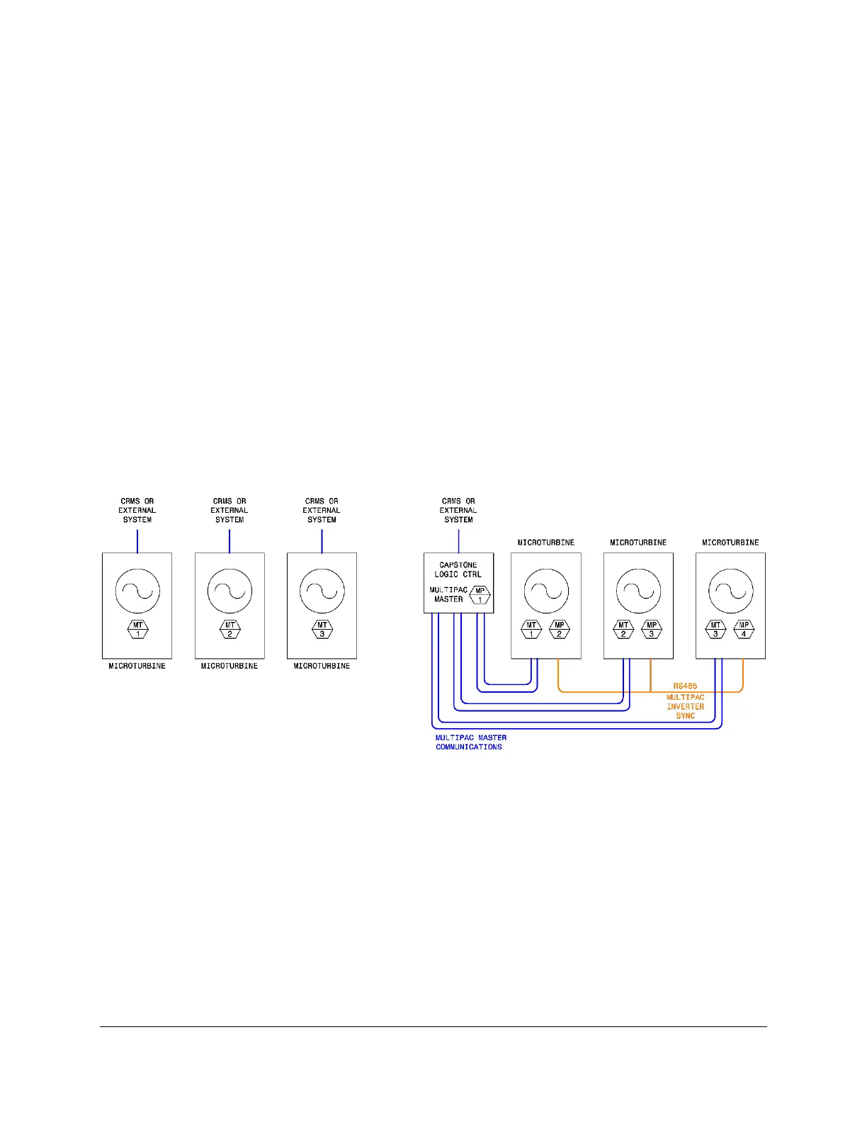
Communication and control for Capstone microturbines is made to a single microturbine or to a
group of microturbines, as shown in Figure 54. External connections are made to the C1000
series controller in the EPDB (see Figure 12). Refer to the C1000S/C800S/C600S Technical
Reference (Table 1) for a detailed description of all C1000 series controller connections. For
multiple units a Capstone Logic Controller (CLC) must be used.
To use CRMS, refer to the CRMS Maintenance Edition Technical Reference (Table 1) and
connect a PC to the C1000 series controller as follows:
1. Connect a Cat 5/Cat 6 cable between the PC Ethernet port and the external Ethernet
connector on the C1000 series controller. Use CRMS to establish communication with
the controller.
2. Use CRMS to establish a TCP/IP connection with the controller.
Figure 54. Communication and Control Overview

 Loading...