EasyManuals Logo

Capstone Microturbine C1000 Series User Manual

Capstone Microturbine C1000 Series
122 pages
To Next Page IconTo Next Page
To Previous Page IconTo Previous Page
Page #117 background imageLoading...
Page #117 background image
Capstone Turbine Corporation • 16640 Stagg Street • Van Nuys • CA 91406 • USA
Installation Guide: Capstone C1000S/C800S/C600S with C1000 Series Controller
480064 Rev C (December 2018) Page 117 of 122
Capstone reserves the right to change or modify, without notice, the design, specifications, and/or contents of this document without
incurring any obligation either with respect to equipment previously sold or in the process of construction.
C1000
Controller
External
TB1-5
TB1-6
DMSC 24 V
TB1-56
TB1-57
TB1-58
TB1-59
DMSC 0 V
DMSC SA LOAD ACTIVE
DMSC RUN ACTIVE CLOSED
TB3-15
TB3-16
TB3-17
TB3-18
TB3-19
TB3-20
REMOTE START/STOP
GC ENABLE
SA ENABLE
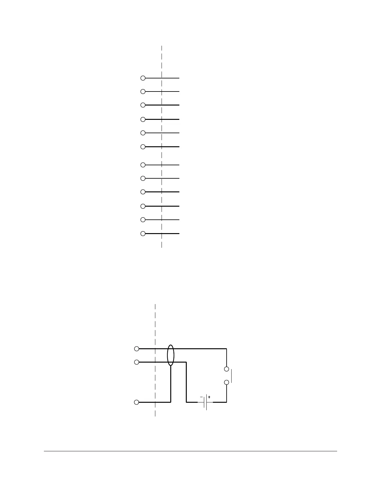
Figure 61. DMSC Terminal Block Connections
8.3.3. Fault Inputs
See Figure 62 for an example fault input connection to the C1000 series controller. Connect the
+24 V side of the contact to TB3-59 and 0 V to TB3-60.
C1000
Controller
External
24 VDC
TB3-59
TB3-60
Chassis
Normally
Open
Contact
Figure 62. Fault Input Connections

Table of Contents

Questions and Answers:

Question and Answer IconNeed help?

Do you have a question about the Capstone Microturbine C1000 Series and is the answer not in the manual?

Capstone Microturbine C1000 Series Specifications

General IconGeneral
BrandCapstone
ModelMicroturbine C1000 Series
CategoryController
LanguageEnglish