Verification
10. Verification
10.1 Introduction
The chapter includes operation and specification test procedures of Chroma 63800 series
AC/DC Electronic Load. The tests are performed via model 63800 or needed equipment.
The equipment required are listed as Table 10-1 shown. About equipment connection please
refer Test Environment Setup and test procedure please refer AC Performance Test. Users
are able to apply verification table under verification test record to check specification.
Performance test is for confirming if Chroma 63800 meets the declaration specification. The
detail operation and programming information, please refer chapter 3 and 8. If there is
maintenance requirement for 63800, please contact worldwide distributors and service
locations on Chroma Website as below:
http://www.chromaate.com/english/contact/default.asp
10.2 Equipment Requirement
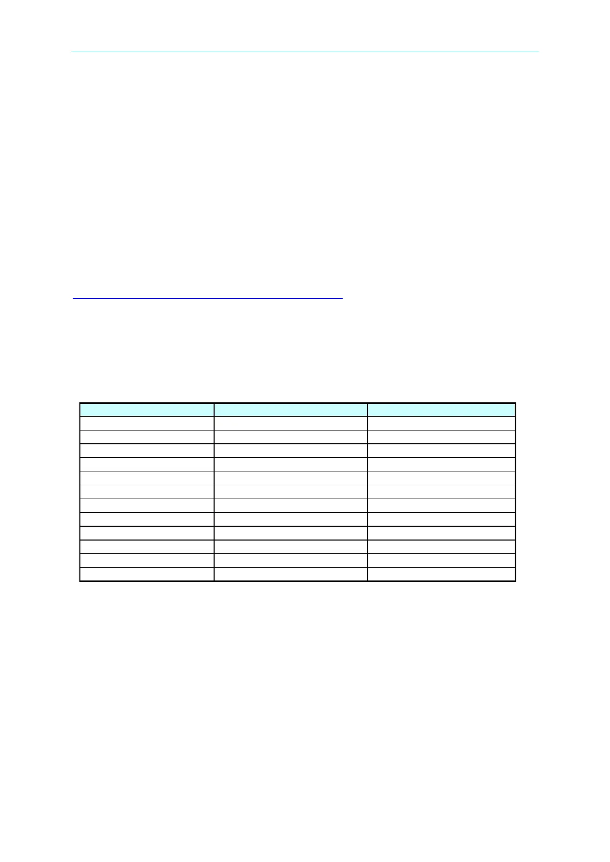
The table listed below are equipment or equivalent for verification.
Table 10-1
BNC to alligator clip cable x 2
10.3 Test Environment Setup
Wiring Description:
1. Figure 10-1: Use AC Source to output for connecting L1 and N. PM3000A consists of
current and voltage terminal. The current terminal used cable needs to withstand current
45A above and withstand voltage 500V DC above. The voltage terminal requires
withstanding voltage 500V DC above, withstanding current 0.1A above. The voltage
terminal of PM3000A, Remote Sense terminal of DVM and AC Load should be at the
same location, moreover it had better close to output location of AC Source. Use BNC to
alligator clip cable to connect DVM Front terminal to V_Mon terminal of AC Load.
However, use another BNC to alligator clip cable to connect DVM Rear terminal to I_Mon
terminal of AC Load.
 Loading...
