Programmable AC/DC Electronic Load 63800 Series Operation & Programming Manual
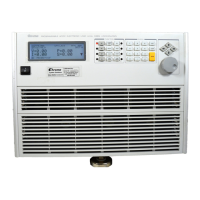
1.5.2 The Rear Panel
The Mainframe rear panel includes ports of RS-232C, System Bus, GPIB, I/O port, two BNC
connectors, a load input socket and an AC LINE socket. Figure 1-3 shows the rear panel of
Mainframe 63800.
Figure 1-3 The Rear Panel of the Electronic Load
Table 1-2 The Description of the Rear Panel
For system input/output control signal
For master/slave control system data communication
A remote controller using GPIB bus is connected to the AC
load through this connector for remote operation.
The 9-pin, D-type female connector transfers control
commands to and from the remote PC for remote operation.
Analog output proportional to voltage waveform.
Analog output proportional to current waveform.
sense terminal
Load terminal is connected to source or UUT for loading. In
addition, voltage sense terminal senses directly at the
terminals of the source to eliminate any voltage drop on the
Power line input is connected to the AC source through this
connector.
It is for switching AC input voltage.
 Loading...
