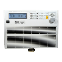
Installation
V
=
1
0
0
. 0
0
P
=
0
. 0
0
I =
0
. 0
0
S
=
0
. 0
0
If any error is found in self-test, the display will stop here. In case of failure, please contact
Chroma sales or service office.
2.4 Application Connection
2.4.1 Load Connections
To satisfy safety requirements, load cables must be large enough not to
overheat while carrying the short-circuit output current of the device
connected to the Electronic Load.
Because the input source is rectified with the single-phase diode bridge circuit, the load
terminals do not have to be identified the input polar direction. The major considerations in
making input connections are the current wire size, length and the voltage sense cables.
The minimum current wire size required to avoid overheating may not be enough to maintain
good regulation. The wires should be large enough to limit the voltage drop less than 0.5V per
lead. The wires should be as short as possible, and bundled or tied together to minimize
inductance and noise. The attached load cables are proposed for testing.

 Loading...