Verification
10.4 AC Performance Test
10.4.1 I monitor & CF Measurement Verification
AC wiring diagram is as Figure 10-1, please switch AC Load to CF only mode. The
procedures are described as follows.
1. Press CONF./LOCAL.
2. Press 1 and ENTER to enter SETUP. (More information about the display, please
refer 3.6.1 BOTH mode).
3. Move the cursors of ▲ and ▼ to “1-5. CF/PF SETTING”.
4. Press direction keys of ◄, ► or turn rotary knob to select “CF” and then press ENTER.
(More information about the display, please refer 3.6.1 BOTH mode).
5. Press CC to return to main screen.
6. AC Source settings are shown as Table 10-2, switch DVM measurement terminal to Rear.
Please follow the model under CC mode to set loading current, I
p(max) & CF. According to
the model to confirm if the values of DVM, Meter & Load meet to that in Table 10-2.
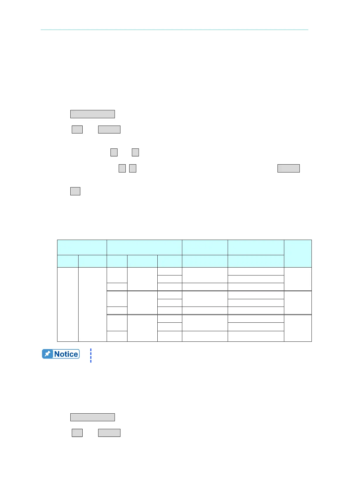
Table 10-2
Load Setting DVM
Model
Ip(max) CF
CF Specification
100 45/440
5
54
0.229~0.271
63802
5
108
0.229~0.271
63803
5
135
0.229~0.271
63804
Source setting in Table 10-2, the frequencies of 45Hz and 440Hz are
tested once for each one. The settings in test item are the same.
10.4.2 CC Mode Setting & Measurement Verification
PF/CF BOTH mode settings are as follows.
1. Press CONF./LOCAL.
2. Press 1 and ENTER to enter SETUP.
 Loading...
