5-2 Installing the 6200 network element
6200 Packet-Optical Platform Installation, Commissioning, and Testing Procedures
Release 1.1 009-6200-201 Draft Issue 1
Copyright
©
2014 Ciena
®
Corporation September 2014
Note 3: The fastening of screws is to be done at both ends uniformly.
Engage two to three threads on both ends before tightening the screws
completely. It is important to align the screws prior to tightening to avoid
screw jamming.
The 6200 NE with Rel 1.1 S/W version supports the following two
configurations for the circuit packs:
• 15G MRO XC circuit pack
• 60G MRO XC circuit pack
This chapter describes the various installation procedures for the combined
chassis (base chassis fitted with the expansion chassis). If you have
purchased only the base chassis, then, some of the information such as the
number of mounting screws, installation toolkit and mechanic kit will differ. For
details, refer to Table 5-1.
Note: While changing the mount angle from 19” to 21” or 23”, do not
handle the combined chassis without the mount angle
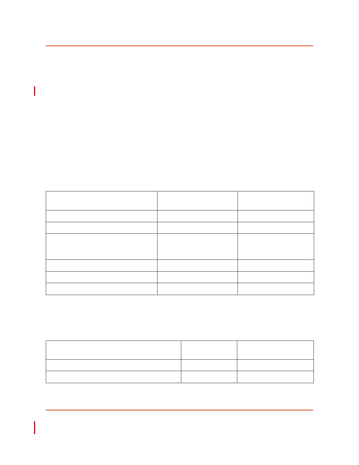
Table 5-1
List of accessories in the mechanical kit
Accessory For base/main chassis For base/main +
expansion chassis
M6 captive screws and nuts 4 8
M6 pan head screws to fix cable routers 4 (required) / 8 (provided) 8 (required) /16 (provided)
M3 screws to fix mount angles (CSK
screws for base/main chassis and
flat-head screws for expansion chassis)
10 (required) / 20 (provided) 22 (required) / 44 (provided)
21” mount angles 2 (1-R and 1-L) 2 (1-R and 1-L)
23” mount angles 2 (1-R and 1-L) 2 (1-R and 1-L)
Cable routers 2 (1-R and 1-L) 4 (2-R and 2-L)
Table 5-2
Number of grounding and power cables required
Accessory For base/main
chassis
For base/main +
expansion chassis
Grounding cables 1 2
Power cables 2 4