GE Voluson E10 Training Manual
© 2017 Conquest Imaging
Table of Contents
Table of Contents ................................................................................... i
Module 1 Introduction .......................................................................... 1
Other Course Offerings ........................................................................1
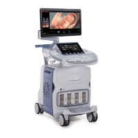
Voluson E10 ................................................................................................... 2
Module 2 System Hardware and Theory .............................................. 3
Signal Flow ..............................................................................................3
System Block Diagram ................................................................................... 4
System Front End Components .............................................................5
Voluson E10 Front End Processor (FEP) .................................................5
RTF - Probe Control Board ......................................................................6
RSE - Pencil Probe Board (optional) ........................................................6
RFM - (RF-Interface & Beamformer) FE Mainboard ...............................6
RFM Board - Interface FPGA.......................................................................... 6
RFM Board - Processing FPGA ....................................................................... 6
RSX - (Beamformer Receiver/Transmitter) Extension Board ..................6
Front End Block Diagram ............................................................................... 7
System Backend Components...............................................................7
Back End Processor (BEP) ........................................................................7
Back End Block Diagram ................................................................................ 8
PC-Motherboard .....................................................................................8
Hard Disk Drive (HDD) .............................................................................9
Distribution of partitions at 500 Gbyte HDD ................................................. 9
Graphic Card ......................................................................................... 10
RTV - Video Management Board .......................................................... 10
External I/O Connection Panel ............................................................. 10
Patient I/O Module .............................................................................. 11
User Console ........................................................................................ 11
Control Panel ........................................................................................ 12
Control Console Positioning ........................................................................ 12
Video Monitor ...................................................................................... 13
Audio .................................................................................................... 13
Power Distribution Components......................................................... 14
Main Power Supply (RSP) ..................................................................... 14
Power Supply Block Diagram ...................................................................... 15
RTB - Distribution Board Bottom ......................................................... 16
Normal Power ON / Shut Down Sequence .......................................... 16
Power On / Boot Up: ................................................................................... 16
Normal Boot-up Process ............................................................................. 17
Boot screen ................................................................................................. 17
Normal Power Off / Shutdown .................................................................... 18
Temperature Control ........................................................................... 18
Module 3 Operating Modes ................................................................ 20