GE Voluson E10 Training Manual
© 2017 Conquest Imaging
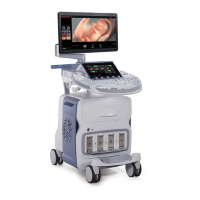
Module 7 Troubleshooting
This module covers common troubleshooting tools and procedures
for the Voluson E10 systems.
Normal Power On/Boot Sequence
The following describes the normal power on/boot sequence for the
Voluson E10 systems
The system has two power switches:
The Circuit Breaker Switch is located on the back of the system
next to the power cord plug-in. This allows to the system power
supply to power up but does not turn on the system itself.
The On/Off button is located on the user control panel at the
front of the system. This switch initates system Bootup.
Connect AC (mains) Power to the Vivid E9/Logiq E9
Before connecting AC Power to the ultrasound unit you should
perform the following preliminary checks of the power cord, voltage
levels and compliance with electrical safety requirements.
Ensure that the wall outlet is of appropriate type, and that the
Mains Circuit Breaker is turned off.
Verify that the power cable is without any visible scratches or any
sign of damage.
Verify that the on-site mains voltage is within the limits indicated
on the rating label near the circuit breaker on the rear of the
unit.
Connect the Power Cable’s to the power Inlet at the rear of the
unit and lock the plug into position with the ACC Clamp.
Note: a probe should be
connected to the system
or the system will boot up
in no mode.
Note: Do not cycle the
circuit breaker ON-OFF-
ON in less than five
seconds. When turning
the circuit breaker off you
must wait until the
ON/OFF button is no
longer lit. The system
should be completely de-
energized before turning
the circuit breaker ON
again.
Note: The E9 functions on
voltages from 100-240V
and 50 or 60Hz. If using
220 V power, a center
tapped power source is
required.